TM9100 Service Manual Description 41
© Tait Electronics Limited August 2005
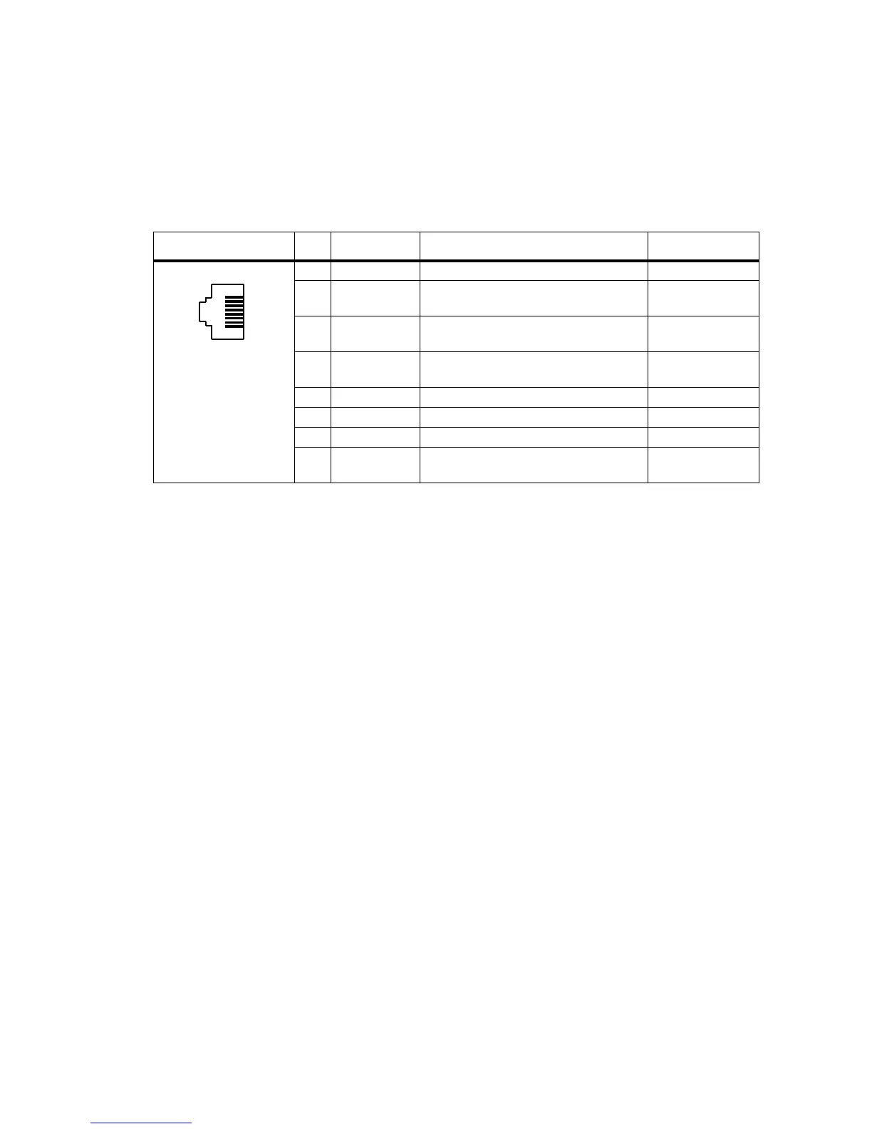
2.3.7 Microphone Connector
The microphone connector of the control head is an RJ45 socket.
When the control head is connected to the control-head connector of the
radio body using the loom provided, the microphone connector uses the
following eight control-head connector signals:
Table 2.6 Microphone connector – pins and signals
Pinout Pin Signal name Description Signal type
1 MIC_RX_AUD Receive audio output. Analog
2+13V8
a
Power supply output. Switched off
when radio body is switched off.
Power
3 MIC_TXD Asynchronous serial port -
Transmit data.
3.3V CMOS
4 MIC_PTT PTT input from microphone. Also carries
hookswitch signal.
Digital
5 MIC_AUD Fist microphone audio input. Analog
6 AGND Analog ground. Analog ground
7 MIC_RXD Asynchronous serial port - Receive data. 3.3V CMOS
8 MIC_GPIO1 General purpose digital input/output. Open collector out
3.3V CMOS in
a. Can be switched or unswitched. For more information refer to “Connector Power Supply Options” on page 85.
B
I
front view
 Loading...


