4-41 2000-OSM, F1
4. On the Manual Temperature Control Mode screen (see Figure 4-38), select the desired field
using the Up and Down cursor keys. Enter two digits for valve numbers (e.g. 04), as some
installations have more than nine valves.
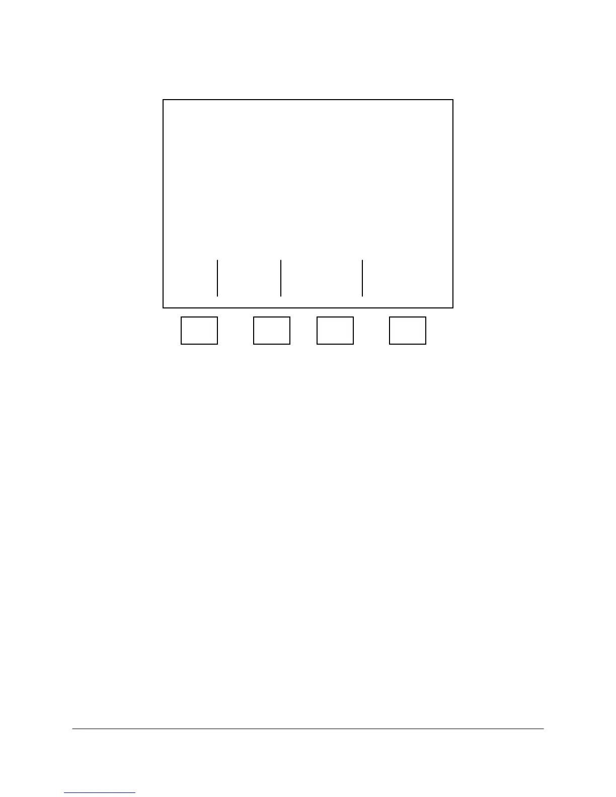
**** Manual Temperature Control Mode ****
Zone Config Actual SP Rate
ISO-OVEN ISO 79.9C 80.0C 0.0
PROG. OVEN PROG/C 220.1C 220.0C 30.0
T/C CELL SWITCH 199.8C 200.0C 10.0
LSV ISO 199.9C 200.0C 10.0
Valve # : [0] Time : 0125
Zone # : 2 State : Pk Back
Set Point: 220.00
Ramp Rate: 30.0000 T-Rating Ver
VALVES : - - - - - - - - T2 290C
Accept Zero Span
Escape Control All All
Point Zones Zones
F1 F2 F3 F4
Figure 4-38. MANUAL TEMPERATURE CONTROL MODE SCREEN
5. After you enter changes in the Set Point or Ramp Rate fields, press the F2 (Accept Control Point)
soft key to save the new data.
Data changes made on the screen go to the DTC Backplane PCB, which compares the new settings
with the application-specific temperature limits. If the new settings fall within the limits, it accepts
them and applies them to the analysis.
If entries in the Set Point or Ramp Rate fields fall outside the set limits, the * TEMP BD ALARM *
flashes on the screen’s message line. Temperature Zone specific alarms also cause the zone name
to flash. To identify the type of alarm, press Escape to return to the Pres & Temp Control Screen,
then press the F4 (Alarms) soft key to display the Alarm Screen. After you note the type of alarm
triggered and consult the Data Package for the set limits, clear the alarm, return to the Manual
Temperature Control Screen, and change the entries to values within the set limits. If the DTC
Backplane PCB accepts the new settings, there will be no * TEMP BD ALARM * display on the
screen after you press the F2 (Accept Control Point) soft key.
Zero All Zones and Span All Zones settings are made in the factory and are not intended to be
changed.
5 Zone Names and Limits Table
This screen allows you to enter low and high alarm limits and change the temperature zone names.
Always check the original application-specific temperature limits listed in the analyzer's Data Package
to validate any changes. To access the 5 Zone Names and Limits Table perform the following steps:
1. On the Background screen, press the F2 (Manual Control) soft key.
2. On Manual Control Mode screen, press the F4 (Press. & Temp. Control) soft key.
 Loading...


