6-30 2000-OSM, F1
Power Distribution
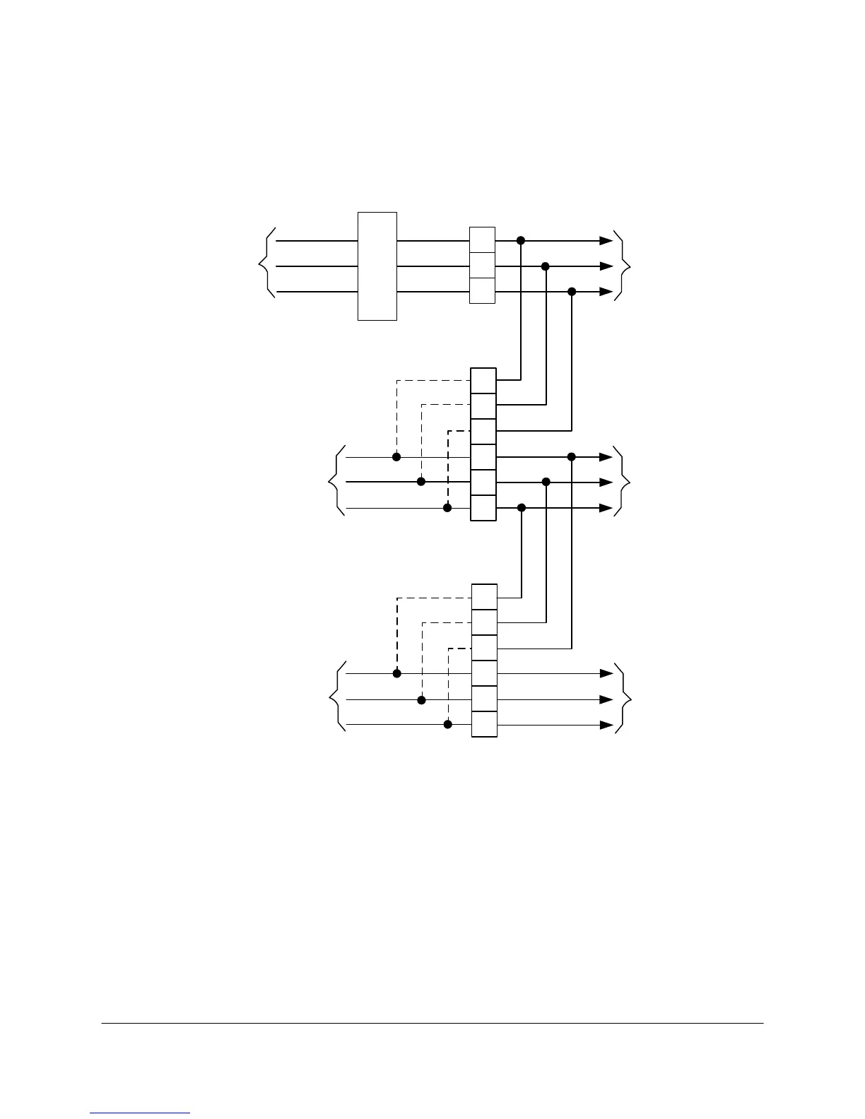
The analyzer uses three power distribution circuits to route the power (see Figure 6-17):
VAC #1, which provides heater power
VAC #2, which powers the electronics through the Power Supply PCB
VAC #3, which power the detectors, solenoid drivers, and EPC
115 to 230 VAC
(Not Filtered
or Conditioned)
1
3
2
TB1
Hot
Neut
Gnd
6
5
1
3
2
J1A
115 to 230 VAC
(Conditioned
or UPS)
3
1
2
6
4
5
J1B
115VAC
(Autoformer)
VAC #1
(to heaters)
VAC #2
(to electronics)
Hot
Hot
VAC #3
(to solenoids
and detectors)
Neut
Neut
Gnd
Gnd
4
RFI
Filter
Jumpers installed when
J1A does not have
separate power source
Jumpers installed when
J1B does not have
separate power source
Figure 6-17. INPUT POWER DISTRIBUTION
If all power supplied to the analyzer comes from a single source it will be connected to TB1.
Instead of input cables there will be jumper plugs installed at J1A and J1B to connect their
distribution circuits to the input power source.
If unconditioned power is routed to TB1 and conditioned power to J1A, then J1B will have a
jumper plug to connect its distribution circuits to J1A.
If unconditioned power is routed to TB1 and an autoformer output is routed to J1B (with J1A
not being connected to source power), then J1A will have a jumper plug to connect its
distribution circuits to TB1.
 Loading...


