2000-OSM, F1 8-63
JP1: When there is only one Chroma I/O PCB in the analyzer, or the board is used as Chroma I/O
PCB #1 in a simultaneous dual detector analyzer, the shunt is installed between pins 1 and 2.
When the board is used as Chroma I/O PCB #2, the shunt is installed between pins 2 and 3.
JP2 through JP6: These jumpers are installed between pins 2 and 3 on the Chroma I/O PCB (later
revisions of this board will have the jumpers hard-wired).
VALCO DIAPHRAGM VALVE REPAIR
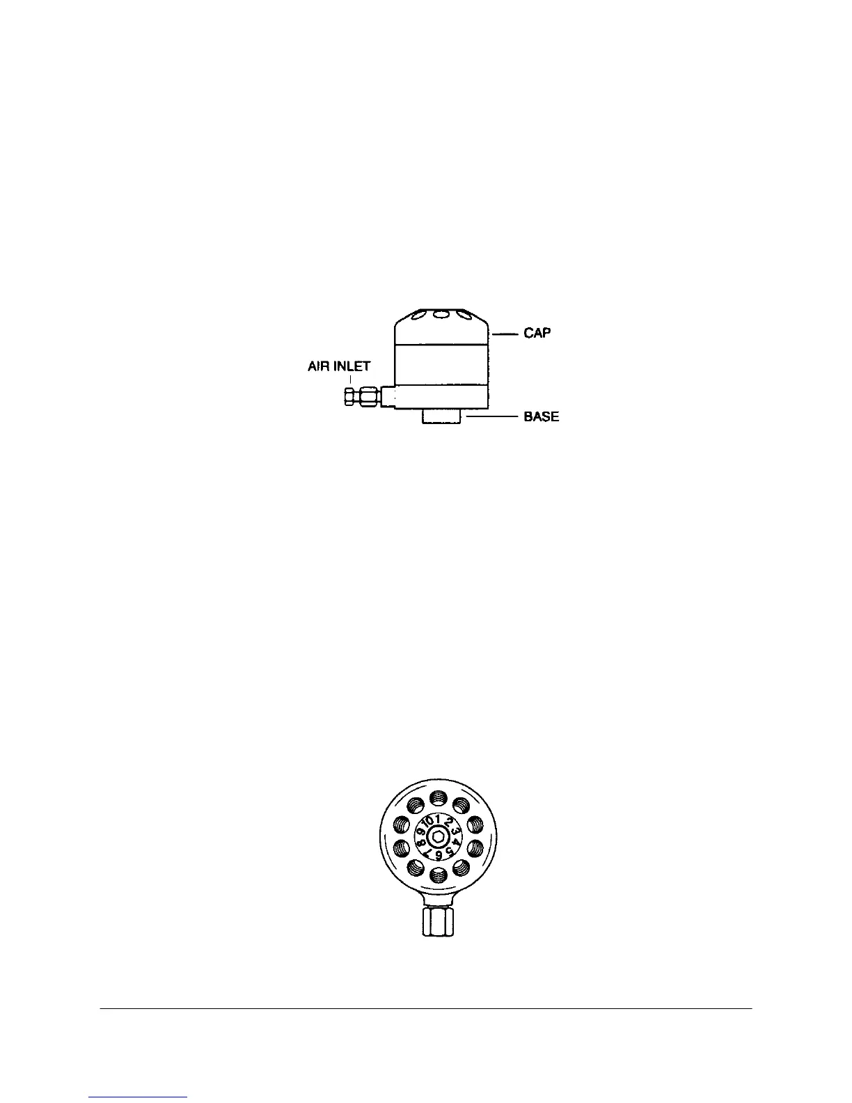
The Valco DV22 ten-port diaphragm valve is used in some analyzers (see Figure 8-39). This
procedure and the accompanying illustrations were reprinted with permission of VICI, Houston, TX,
USA.
Figure 8-39. VALCO 10-PORT DIAPHRAGM VALVE
Removing the Valve
1. Tag all valve connections.
2. Using a 1/4-inch wrench, remove the connections from the valve cap.
3. Using a 7/64-inch hex key wrench, loosen the clamp ring screw.
4. Remove the valve from the clamp ring and take it out of the analyzer.
Repairing the Valve
1. Place the valve on a clean work surface.
2. Note the location of port 1 on the valve, opposite the air inlet (see Figure 8-40).
Figure 8-40. CAP ORIENTATION
 Loading...


