2000-OSM, F2 8-45
CAUTION
Be sure that the EPC Control Assembly has cooled to ambient temperature
(approximately one hour) before proceeding.
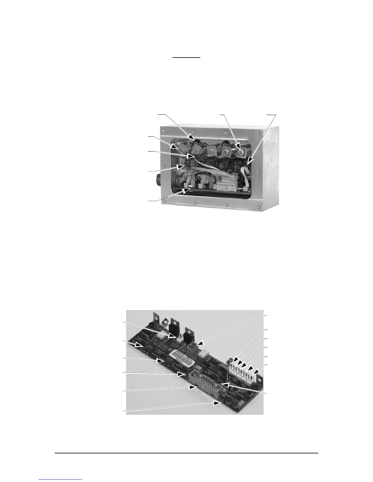
The Zones are arranged in the EPC Control Assembly enclosure with Zone one on the left
and Zone 5 on the right (see Figure 8-21).
Control PCB
Proportional Valve,
Zone 1
Sensor PCB,
Zone 1
Heater
Sensor PCB,
Zone 5
Proportional Valve,
Zone 5
Screw and
Washer
Figure 8-21. EPC CONTROL ASSEMBLY COMPONENTS
1. Perform the “Preparation” procedure.
2. Remove the two screws holding the EPC cover and remove the cover panel.
3. Remove the ten screws holding the EPC Control Assembly cover using ABB Tool
TL1009 and remove the cover. Be careful not to damage the flame-proof or explosion-
proof surfaces of the cover or the body of the Control Assembly.
4. Unplug the large ribbon cable from the Control PCB and fold it back to your left and out of
the way (see Figure 8-22).
AC Power Cable from
Backplane PCB J44
Sensor PCB Cable,
Zone 1
Sensor PCB Cable,
Zone 2
Sensor PCB Cable,
Zone 3
Sensor PCB Cable,
Zone 4
Sensor PCB Cable,
Zone 5
Large Ribbon Cable
from EPC
Multibus PCB
Heater Cable
Valve Cable, Zone 5
Valve Cable, Zone 4
Valve Cable, Zone 3
Valve Cable, Zone 2
Valve Cable, Zone 1
Figure 8-22. EPC CONTROL PCB CABLING
 Loading...


