4-67 2000-OSM, F1
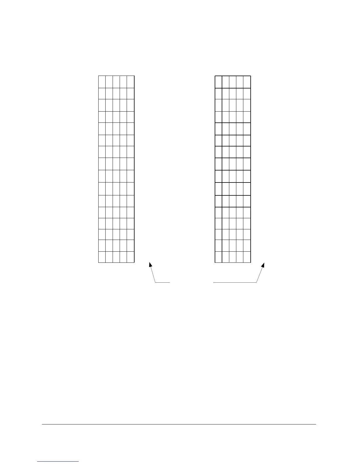
The first five switch positions on SW1 (labeled 0 through 4 on the PCB), determine the analyzer's
address. Switch positions 6, 7 and 8 are always ON ("1"). Figure 4-58 shows how to identify the
address from the switch positions.
#10
#6
#22
#7
#23
#9
#25
#26
#1
#17
#8
#24
#2
#18
#3
#19
#4
#20
#5
#21
#11
#27
#12
#28
#13
#29
#14
#30
#15
#31
#16
#32
Address
Switch No. Switch No.
11111
54321
11110
11101
11100
11011
11010
11001
11000
10111
10110
10101
10100
10011
10010
10001
10000
01111
54321
01110
01101
01100
01011
01010
01001
01000
00111
00110
00101
00100
00011
00010
00001
00000
Figure 4-58. ADDRESS IDENTIFICATION WITH SW1
NOTE
Be sure to save the tables to E
2
PROM before cycling the analyzer power. Each
time you use one of these address switches, you must turn the unit OFF and back
ON again to initialize the switch selections.
Switch SW2 on the LO COMM PCB provides two other user-selected switch settings. The PCB labels
these “No Analyzer” and “Lock Out Remote.” The OFF position is to the left of SW2 as it is shown in
Figure 4-57.
NOTE
Be sure to save the tables to E
2
PROM before cycling the analyzer power. Each
time you use either of these switches, you must turn the unit OFF and back ON
again to initialize the switch selection.
 Loading...


