2000-OSM, F1 8-55
Backplane PCB
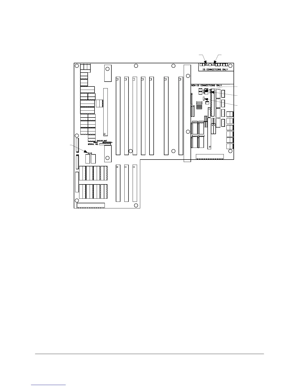
The Controller Backplane PCB has six jumpers to set up (see Figure 8-27).
JP1
JP5
JP3
JP2
JP6
JP4
Figure 8-27. BACKPLANE PCB JUMPER LOCATIONS
Jumpers JP1 and JP5 are used to bypass pressure switch connection points for certain analyzer
configurations. Since the purge switches are daisy chained in series, it is necessary to jumper across
switches that are not connected. Jumper JP1 has its shunt installed between pins 1 and 2 for
standard or Sparger oven usage; the shunt is installed between pins 2 and 3 for temperature
programmed applications. Jumper JP5 has its shunt installed between pins 1 and 2 for single purge
area; the shunt is installed between pins 2 and 3 for dual purge location applications.
Jumpers JP2, JP3 and JP6 are associated with the purge alarm switch closures applied to the
Chroma I/O PCB. Jumper JP2 has its shunt installed between pins 1 and 2 for X Purge applications
only; the shunt is installed between pins 2 and 3 for Y or Z purge applications. Jumper JP3 has its
shunt installed between pins 1 and 2 for standard analyzers; the shunt is installed between pins 2 and
3 for temperature programmed and Sparger applications. Jumper JP6 has its shunt installed
between pins 1 and 2 for single purge configurations; the shunt is installed between pins 2 and 3 for
dual purge applications.
Jumper JP4 is used to connect two detectors to a single Chroma I/O PCB. The location of the jumper
shunt depends on the revision of the Backplane PCB. Backplane PCBs that do not have JP5 and
JP6 are artwork revision D or earlier, while those having JP5 and JP6 are artwork revision E or later.
• For revision D or earlier, the shunt is installed between pins 1 and 2 when the outputs of two
detector amplifiers are applied to a single Chroma I/O PCB; the shunt is installed between pins 2
and 3 for normal operation (a Chroma I/O PCB dedicated to a single detector amplifier).