2000-OSM, F1 6-29
CONTROLLER PROBLEMS
Input Power
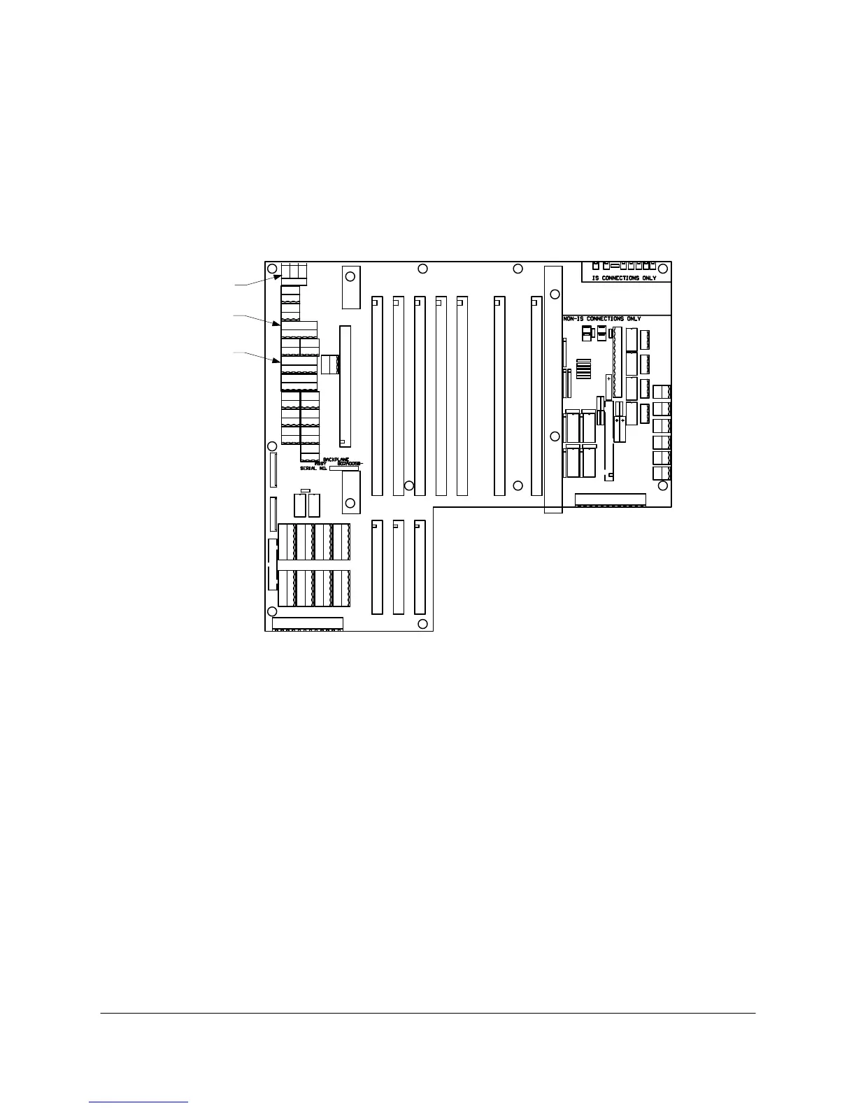
Input power is connected to one or more of the following locations on the Backplane PCB in the
Controller Housing (see Figure 6-16):
TB1, which is called VAC #1
J1A, which is called VAC #2
J1B, which is called VAC #3
TB1
J1A
J1B
1 2 3 4 5 6
TB1
J1A
J1B
1 2 3 4 5 6
Figure 6-16. BACKPLANE PCB POWER CONNECTIONS
Input power is 115VAC. This may be supplied directly as 115VAC or stepped down from a higher
voltage. The input voltage may be conditioned or supplied from an uninterruptible power supply
(UPS). Each of these choices, made at the time of sale, affects how the power is brought into the
analyzer.
 Loading...


