8-32 2000-OSM, F1
Replacing the Burner Block
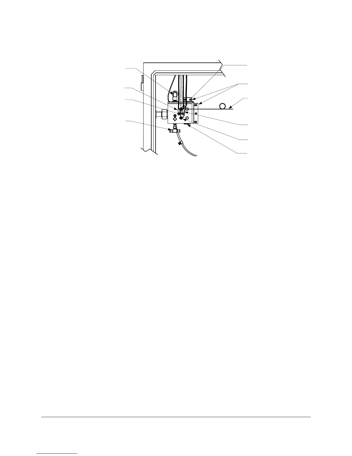
Refer to Figure 8-13 as you perform this procedure.
Sulfur Addition
Wafer
Thermocouple
Heater
Sample
Mounting
Screws
Vent Line
H2 and/or
Carrier
Thermocouple
Heater
Temp Sensor
(804A005-3 only)
Figure 8-13. BURNER BLOCK
1. Remove power from the analyzer.
2. Turn off oven air to the isothermal oven and allow all temperature zones to cool.
3. Turn off air supply to air cleanup unit.
4. Open the isothermal oven door.
5. Disconnect the thermocouple leads from the Burner Block.
6. Disconnect the heater leads from the Burner Block.
7. Disconnect the temp sensor leads from the Burner Block, if installed.
8. Disconnect the sample line from the Burner Block.
9. Disconnect the vent line from the Burner Block.
10. Disconnect the hydrogen (H2) and carrier lines from the Burner Block.
11. Remove the bracket screws that fasten the Burner Block to the oven.
12. Slide the Burner Block off the end of the Photomultiplier Assembly and remove the Burner Block
from the oven.
13. Install the new Burner Block in reverse order of removing it.
 Loading...


