2000-OSM, F1 2-25
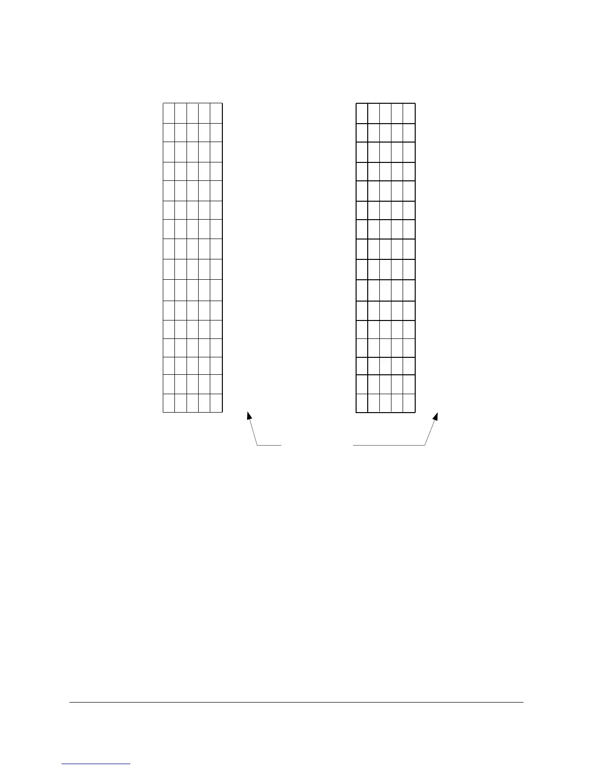
5. Set the switch positions to the desired remote number, using Figure 2-15 as a guide.
#10
#6
#22
#7
#23
#9
#25
#26
#1
#17
#8
#24
#2
#18
#3
#19
#4
#20
#5
#21
#11
#27
#12
#28
#13
#29
#14
#30
#15
#31
#16
#32
Remote No.
Switch No. Switch No.
11111
54321
11110
11101
11100
11011
11010
11001
11000
10111
10110
10101
10100
10011
10010
10001
10000
01111
54321
01110
01101
01100
01011
01010
01001
01000
00111
00110
00101
00100
00011
00010
00001
00000
Figure 2-15. REMOTE NUMBER IDENTIFICATION WITH SW1
6. Insert the Chroma I/O PCB into slot 2 of the Card Cage and make sure the PCB is securely in
place.
7. Close and lock the GCC front panel.
8. Turn power to the analyzer ON at the circuit breaker.
The local control options are manual control, view only, and screen saver, using SW1 positions 6, 7,
and 8 (SW1 positions 6 and 7 interact).
• Setting SW1-7 to OFF locks the screen in a “view only” mode; you cannot edit any tables or
functions. Setting SW1-7 to ON disables the “view only” function.
• SW1-6 provides manual control but does not let you update tables. Setting SW1-6 to OFF
enables manual control, but only when SW1-7 is in the ON position. When SW1-7 is set of OFF
this overrides the setting of SW1-6.
 Loading...


