4-5 2000-OSM, F1
Flame Photometric Detector (FPD)
Flame photometric detection works on the principle that when sulfur is burned in a hydrogen-rich
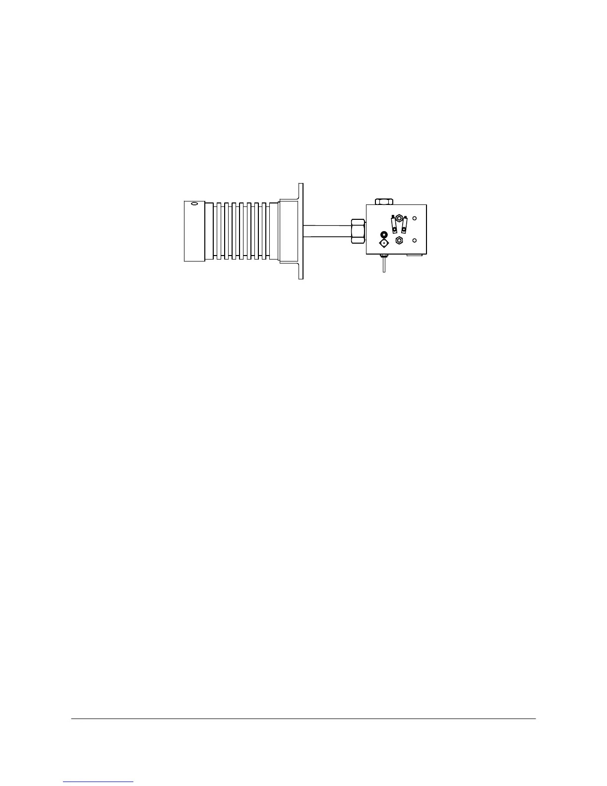
atmosphere, luminescence (light) characteristic to sulfur is produced. The FPD cell (see Figure 4-5)
consists of a teflon burner chamber equipped with a spark ignition system, and a photomultiplier tube
which is thermoelectrically temperature controlled. A narrow bandpass filter optically connects the
burner chamber and the photomultiplier tube. An exponential amplifier conditions and amplifies the
photomultiplier tube output to provide a linear output over a wide dynamic range. Sulfur addition
permits accurate measurement of low-level sulfur compounds.
Burner BlockPhotomultiplier Tube
Figure 4-5. FLAME PHOTOMETRIC DETECTOR
When a sulfur compound passes through the hydrogen-rich flame, strong luminescence occurs
between 320 and 460 nm. The narrow band-pass filter allows a sulfur spectra-centered transmission
at 394 nm ± 5 nm to achieve a specific ratio of sulfur to non-sulfur compounds between 10,000 and
30,000:1. A photomultiplier tube views the filtered light and outputs a voltage proportional to the
intensity of the filtered luminescence. For maximum sensitivity, the detector is optimized with respect
to temperature, gas flow rates, and bias voltage on the photomultiplier tube.
Because the amount of sulfur in the sample is very small, a sulfur addition module provides a
standard level of sulfur. This keeps the sulfur readings above the noise level within the analyzer.
When the analyzer processes a sulfur compound, the sulfur in the sample adds to the standard sulfur,
providing a level more easily measured by the photomultiplier tube.
Intercolumn Detector
The intercolumn detector measures the total sample elution profile before complete component
separation takes place in the analytical column, or as a part of a heart cut, or backflush valve switch.
It is generally used as a setup aid during installation or after rework. While the exact location of the
intercolumn detector is application dependent, it can be connected between the sample valve and the
column, between the column and the analytical detector, or between the sample valve and the
backflush valve.
Sequential Dual Detectors
Sequential dual detectors allow one analyzer to provide the detection output of two detectors to meet
speed or sensitivity requirements. Because these detectors function sequentially using any two
detectors, one Chroma I/O Board controls both detectors and their signal output in series. Valve
switching in the method tables determines which detector's data will be processed by the Chroma I/O
Board at any given time. Sample flow through the detectors is application-specific; the details are
shown in the Data Package.
 Loading...


