200 Rockwell Automation Publication 1444-UM001D-EN-P - June 2018
Chapter 6 Configure Analog Outputs
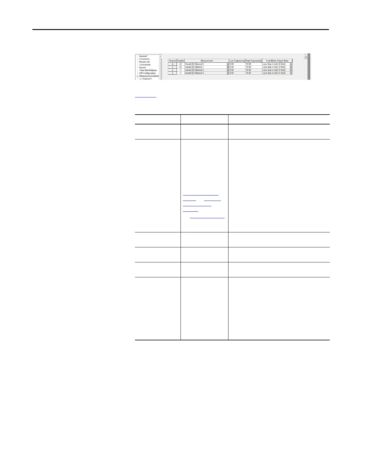
Output Configuration Page
Page Overview
Tab le 42 is a list of the different output configurations.
Table 42 - Output Configuration
Parameter Values Comment
Enable Enabled (checked) or Not
Enabled (not checked)
Check the box to enable output from each respective
4…20 mA output channel.
Measurement Available selections are
dependent on the
Channel Type and the
Channel Measurement
Type for the channel that
is associated with each
measurement.
See Define Module
Functionality page in
Module Definition on
page 92 and Hardware
Configuration on
page 112.
See Table 43 on page 201
to view all available
settings.
Select the measurement to be output on the referenced
Analog Module channel.
Low Engineering Any Enter the value, in Engineering Units, which is to
correspond to an output magnitude of 4 mA.
High Engineering Any Enter the value, in Engineering Units, which is to
correspond to an output magnitude of 20 mA.
Units — Displays the Engineering Units for the selected
measurement.
Fault Mode Output State Select from:
•No action
•< 4 mA
•> 20 mA
Select the desired behavior on fault.
Outputs the measured value, regardless of the fault
condition.
If “< 4 mA” the output is driven to 2.9 mA.
If “> 20 mA” the output goes to ~21 mA.
Faults that result in the defined behavior include:
• Transducer Fault (for the channel that is associated with
the measurement)
• Expansion Bus Failure
• Expansion Module Self-Check Fail

 Loading...