50 Rockwell Automation Publication 1444-UM001D-EN-P - June 2018
Chapter 2 Install the Dynamix 1444 Series Monitoring System
Wiring the Main Module
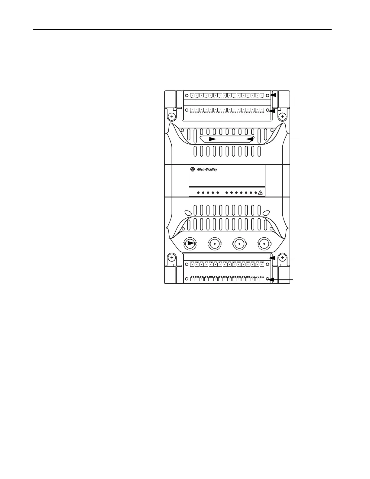
An installed system has four removable 16-way terminal connectors, two
interfacing directly to the removable module, and two to the terminal base.
The base and module-mounted headers are able to accept either a screw or
spring terminal connector.
Figure 8 - Main Module Connectors
Allocations to the base or module are broadly based on the following
functional requirements:
• Wide-range 24V DC power connections are direct to the base so that
they are unaffected by module removal.
• Main signal inputs/outputs and relay connections are direct to the
module to minimize connection length and number of interfaces.
Each connector is keyed to its respective mating header (two per connector)
and each of the terminals is uniquely numbered. Some external links can be
made between terminals, depending on application requirements, to enable,
for example, a transducer power supply for a 2-wire transducer connection.
1444-DYN04-01RA
RUNPWR
Dynamic Measurement
Ethernet Port 2
+ Status
indicators
Ethernet Port 1 +
Status Indicators
BNC Buffered
Outputs (0–3)
Upper Base
Connector
Upper Module
Connector
Lower Base
Connector
Lower Module
Connector

 Loading...