28 Rockwell Automation Publication 1444-UM001D-EN-P - June 2018
Chapter 2 Install the Dynamix 1444 Series Monitoring System
Wiring Categories and Routing
The following wiring categories are defined to help with proper segregation of
wires and cables as part of the planning process for system layout and
installation to promote noise immunity.
Use shielded/screened
cables
• For the analog sensor input, each channel must be separately shielded (one shield for
each channel in a multi-core cable).
Properly terminate the
shield wires
• Keep the unshielded part of the cables as short as possible. It is ideal if only the last 100
mm (3.94 in) of the cable is unshielded.
• Preferably, use an EMC cable gland to obtain a 360° ground connection to the
enclosure. Alternatively, connect the shielded wire directly after entering the cabinet
or the enclosure on a grounded bus bar and fix it with a cable clamp.
– The modules provide SHIELD terminals that can be used for shield wire termination.
However, from a performance perspective, the previously described methods are
preferred. The SHIELD terminals are connected together, but otherwise isolated
from all module circuitry and the DIN rail. The installer uses one or more of the
SHIELD terminals to connect to a ground of their choosing
• Use a direct connection from the cable shield to the protective conductor.
• Connect only one end of the shield to ground; for hazardous area systems, preferably at
the field end. For known EMI hot-spots, use of overall conduit or double-shielded
cabling with shield that is grounded at both ends is preferred.
• When an additional junction box is used for dividing a multi-core cable into separate
cables, verify that the cable shields are isolated from the metal enclosure of the
distribution box. (The distribution box must be made of metal.)
Make a uniform
reference potential
(reference ground)
Avoid ground loops by connecting the installations and cabinets to a central ground
conductor
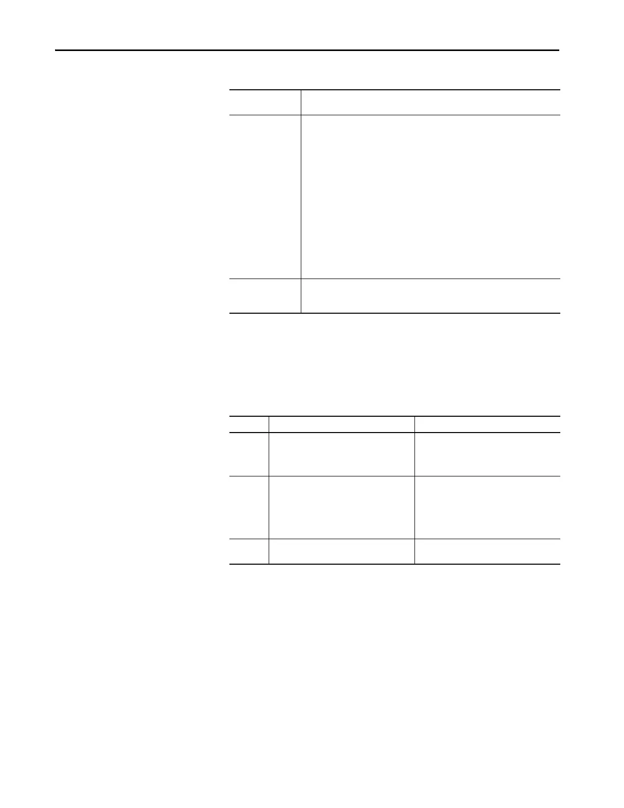
Category Group Description Examples
1 Control and AC Power – High-power conductors
that are more tolerant of electrical noise than
category 2 conductors and can also cause more
noise to be picked up by adjacent conductors.
• AC power lines for power supplies and I/O
circuits
• High-power digital AC I/O lines
• High-power digital DC I/O lines
2 Signal and Communication – Low-power
conductors that are less tolerant of electrical
noise than category 2 conductors. They also
cause less noise to be picked up by adjacent
conductors (they connect to sensors and
actuators relatively close to the I/O modules).
• Analog I/O lines and DC power lines for analog
circuits
• Low-power digital AC/DC I/O lines
• Low-power digital DC lines
• Communication cables
3 Intra-enclosure – Interconnect the system
components within an enclosure.
•Low voltage DC power cables
• Communication cables
Table 4 - EMC Precautions

 Loading...