88 Rockwell Automation Publication 1444-UM001D-EN-P - June 2018
Chapter 2 Install the Dynamix 1444 Series Monitoring System
Start the Module and
Perform a Self-test
After the modules are wired, power can be applied to test the installation. At
power-up, each module performs an initial Self-test.
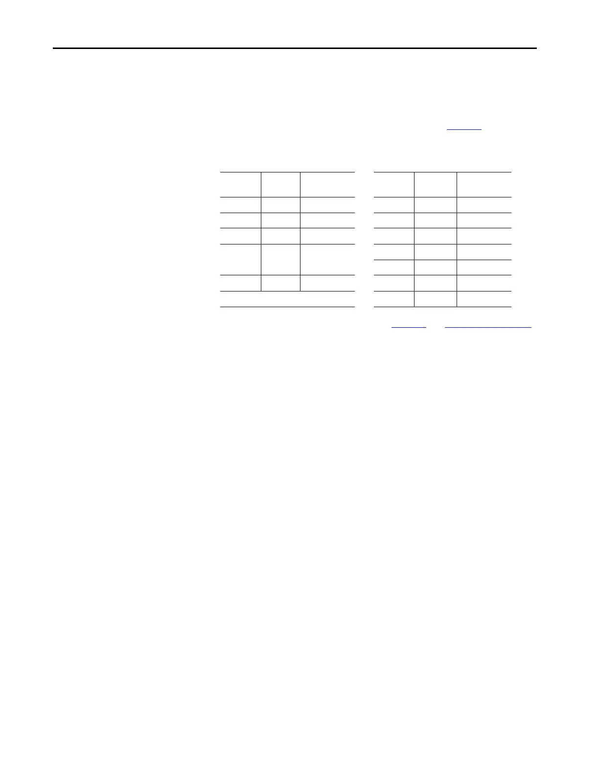
After the Self-test cycle the modules move to an idle state until a configuration
is downloaded, and a connection is made to a controller. Table 11
describes the
status indicators:
Table 11 - Dynamic Measurement Module
If the status indicators are not as shown in Tab le 11 , see Table 79 on page 308.
Status
Indicator
Color Behavior Status
Indicator
Color Behavior
PWR Green Solid DSP Green Flashing
RUN Green Flashing OK Green Solid
MS Green Solid CH0 Green Solid
NS Green Solid or Flashing CH1 Green Solid
CH2 Green Solid
OS Green Solid CH3 Green Solid
RLY Green Solid

 Loading...