64 Rockwell Automation Publication 1444-UM001D-EN-P - June 2018
Chapter 2 Install the Dynamix 1444 Series Monitoring System
Lower Base Connector
Shield
Shield connections are provided as a termination point for cable screens/
shields; one or more can be used to connect Shield to a local ground of your
choosing.
Logic Inputs
The DYN module includes two logic inputs, 0 and 1.
For any of the first five selections that are shown in Figure 17
, when used as a
control, the digital inputs are TRUE (high) when the circuit between the
controls pins (25 and 26 or 29 and 30) is OPEN.
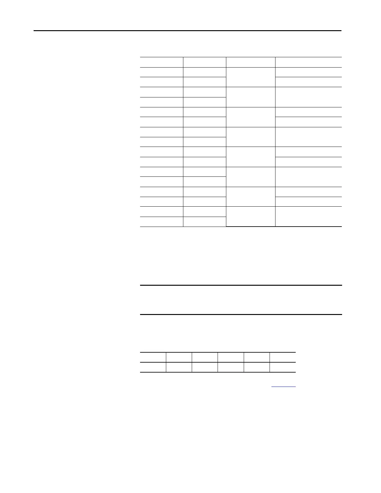
Terminal Name Application Description
17 T0SIG Tach 0 Tach 0 Signal
18 T0RET Tach 0 Return
19 Shield Shield Shields
20 Shield
21 T1SIG Tach 1 Tach 1 Signal
22 T1RET Tach 1 Return
23 Shield Shield Shields
24 Shield
25 L0SIG Logical Input Input 0 Signal
26 L0RET Input 0 Return
27 Shield Shield Shields
28 Shield
29 L1SIG Logical Input Input 1 Signal
30 L1RET Input 1 Return
31 Shield Shield Shields
32 Shield
IMPORTANT There is no internal connection between the Shield Bus and ground. A
separate connection must be made between one terminal shield pin and a
suitable ground location.
25 26 27 28 29 30
L0SIG L0RET L1SIG L1RET

 Loading...