Rockwell Automation Publication 1444-UM001D-EN-P - June 2018 77
Install the Dynamix 1444 Series Monitoring System Chapter 2
Allocations to the base or module are broadly based on the following
functional requirements:
• Signal inputs/outputs and relay connections are direct to the module to
minimize connection length and number of interfaces.
• The base connectors provide mainly Shield connections. Notice that the
same base part is used across all three types of expansion module.
Each connector is keyed to its respective mating header (two per connector)
and each of the terminals is uniquely numbered.
Relay Expansion Module
There are four SPDT relays included in the relay output module (0...3) with
the three contact connections for each being made available at the module
terminals.
NC – Normally closed
C – Common
NO – Normally open
‘Normal’ is the relay contact state when unpowered.
The base part carries mainly Shield connections that are provided as a
termination point for cable screens/shields. In addition, one or more must be
used to connect Shield to a local ground of your choice.
Do not make any connections to terminals 9, 10, 19 or 24.
The relay connections can carry high voltage.
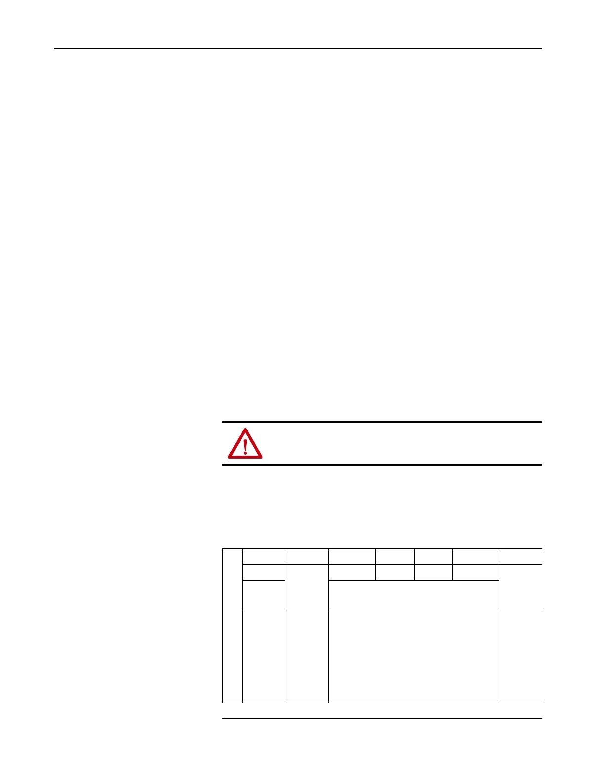
Upper Base Connector
Terminal 24 23 22 21 20 19
Name NOT USED SH SH SH SH NOT USED
Application Shield
Description
Do not connect
Cable shield connection points
Do not connect

 Loading...