56 Rockwell Automation Publication 1444-UM001D-EN-P - June 2018
Chapter 2 Install the Dynamix 1444 Series Monitoring System
Shield Connections
By design, the module is isolated from ground. All shield connections on this
connector and the lower base connector are common to one another (a “shield
bus”), but otherwise isolated.
Shield connections are provided as a termination point for cable screens/
shields, one or more can be used to connect the shield bus to a local ground of
your choice.
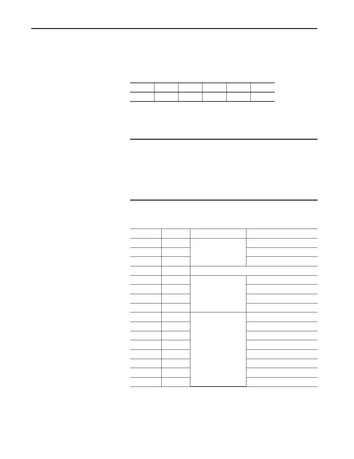
Upper Module Connector
64 63 62 61 60 59
Shield Shield Shield Shield Shield Shield
IMPORTANT When working with the shield bus, remember the following:
• The shield bus of each main and expansion module must be individually
connected to ground by at least one shield pin that is wired directly to
ground.
• For installations where EMI problems are identified, or are anticipated,
wire cable shields directly to ground rather than to the shield bus of the
module.
Terminal Name Application Description
33 NO Relay Outputs Normally Open
34 C Common
35 NC Normally Closed
36 SPARE Do not connect
37 O1L Opto-isolated Outputs Output 1 Low
38 O1H Output 1 High
39 O0L Output 0 Low
40 O0H Output 0 High
41 RET Buffered Outputs Channel 3 Return
42 BUFF3 Channel 3 Signal
43 RET Channel 2 Return
44 BUFF2 Channel 2 Signal
45 RET Channel 1 Return
46 BUFF1 Channel 1 Signal
47 RET Channel 0 Return
48 BUFF0 Channel 0 Signal

 Loading...