Rockwell Automation Publication 1444-UM001D-EN-P - June 2018 43
Install the Dynamix 1444 Series Monitoring System Chapter 2
Mount the Terminal
Base Unit
The following generic DIN rail mounting scheme applies to all terminal base
mounting.
Dynamix 1444 Series terminal bases are mounted using two pairs of screws, the
“DIN rail set screws” and the “Bottom set screws” (see Figure 5
). The screws
that are included are as follows:
The screw lengths are designed to accommodate mounting to standard 35 x 7.5
mm (1.38 x .30 in.) DIN rail. If mounting directly to a panel, or otherwise
require another length screw, then the screws that are provided can be replaced.
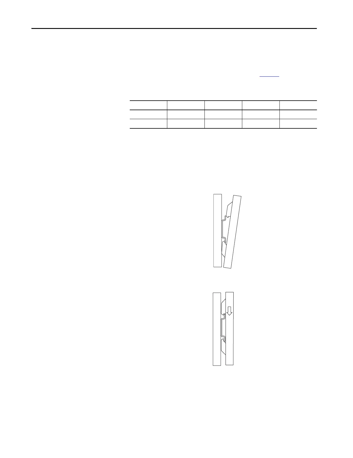
1. Hook the base assembly from the bottom under the DIN rail. The
presence of coding switches identifies the bottom side of the terminal
base.
2. Hook over the top and let gravity drop the terminal base into place.
Table 6 - Dynamix 1444 Series Terminal Base Screws
Application Type Thread Length Phillips Drive
DIN rail set screws DIN7985 M3x0.5 mm 20 mm (0.787 in) #1
Bottom set screws DIN7985 M3x0.5 mm 22 mm (0.866 in) #1

 Loading...