Rockwell Automation Publication 1444-UM001D-EN-P - June 2018 33
Install the Dynamix 1444 Series Monitoring System Chapter 2
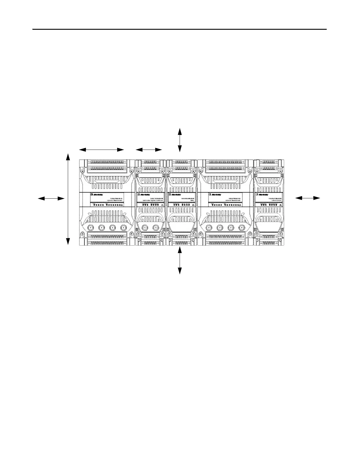
System Space and Clearance Requirements
Design and layout of the system enclosures is a key consideration in any
installation. Verify that there is sufficient space for access to (and fitting/
removal of ) the top and bottom connectors, and a wiring/cable ducting
scheme that maintains appropriate separations.
For proper airflow and installation of the module, the following minimum-air
space requirements must be maintained around the system.
Figure 2 - Clearance Requirements
The 50 mm/2 in. clearance above and below the modules, in combination with
45° angled, pluggable connections, provides for:
• Use of tooling to make/remove electrical connections
• Visible wire identification
• Sufficient physical space to insert/remove pluggable connections
• Optimized air volume per module in relation to thermal performance
50 mm
(2 in.)
50 mm
(2 in.)
25 mm
(1 in.)
25 mm
(1 in.)
158 mm
(6.22 in.)
102 mm
(4.92 in.)
54 mm
(2.13 in.)
Height: 125 mm (4.92 in.)

 Loading...