Rockwell Automation Publication 193-UM015E-EN-P - October 2015 199
Operating Modes Chapter 5
Timing Diagram
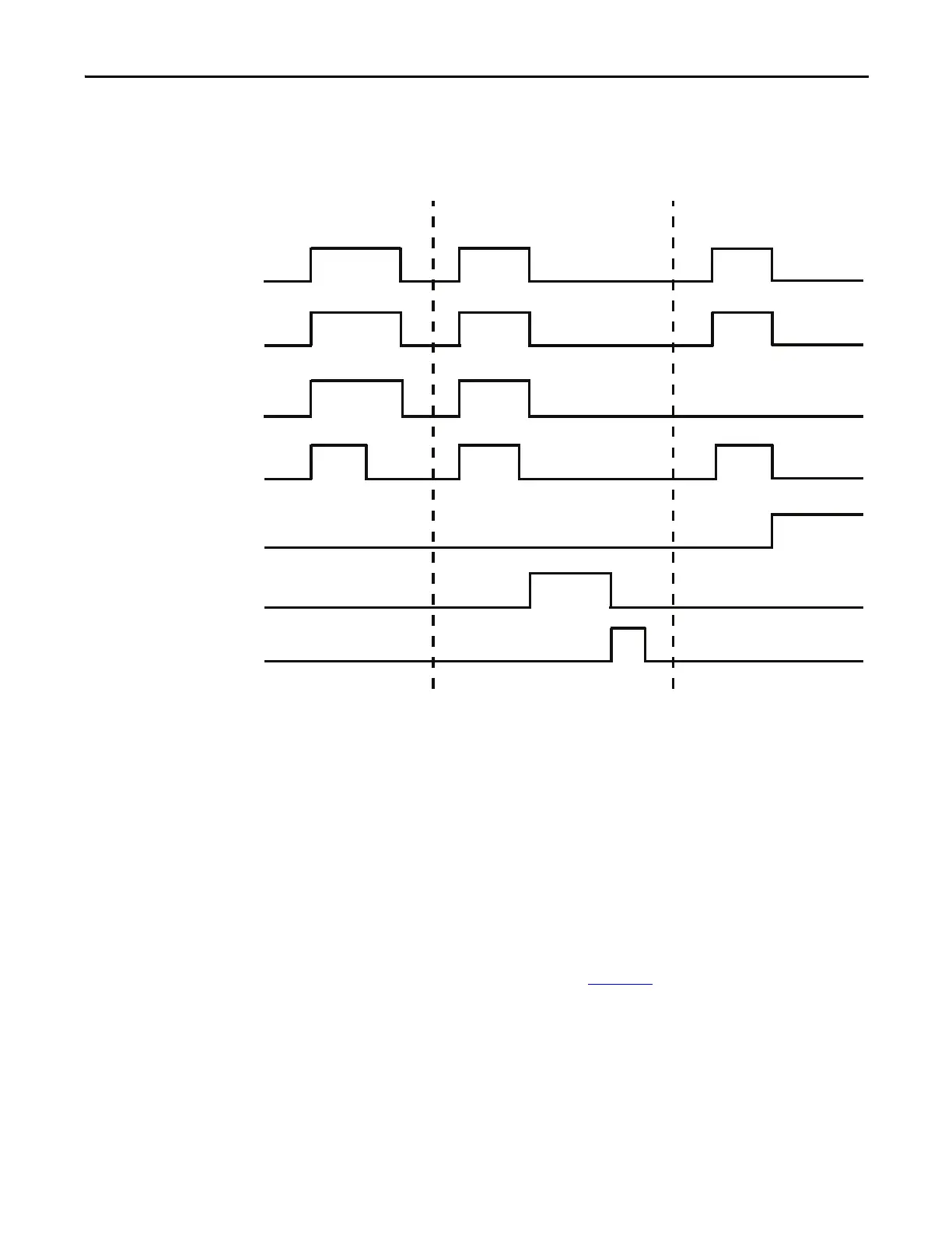
Figure 104 - Non-reversing Starter (Network & Local I/O) with Feedback – Two-wire Control
Timing Diagram
Non-reversing Starter (Network & Local I/O) – Three-wire Control
The E300 relay’s Operating Mode Non-Reversing Starter (Network& Operator
Station) – Three Wire Control (Parameter 195 = 18) uses the network tag
LogicDefinedPt00Data in Output Assembly 144 in Remote control mode and
Input 1 & Input 2 in Local control mode to control Relay 0, which controls the
contactor coil. LogicDefinedPt00Data is a maintained value, so the non-
reversing starter remains energized when LogicDefinedPt00Data has a value of 1
in Remote control mode. You can program the appropriate state of the starter
when communication is lost in Remote control mode by using the Network
Communication Fault and Network Communication Idle parameters
(Parameters 569 – 573) described in Chapter 4
.
Local control mode uses a normally open momentary push button that is wired
to Input 1 to energize Output Relay 0, which controls the contactor coil. A
normally closed momentary push button that is wired to Input 2 is used to de-
energize Output Relay 0. The non-reversing starter only energizes if Input 2 is
active and Input 1 is momentarily active.
Trip Event Feedback Timeout
Feedback
Relay 0
Timer
Feedback
Timeout Trip
Trip Status
Trip Reset
Normal Operation
Run/Stop

 Loading...


