306 Rockwell Automation Publication 193-UM015E-EN-P - October 2015
Chapter 5 Operating Modes
Wiring Diagram
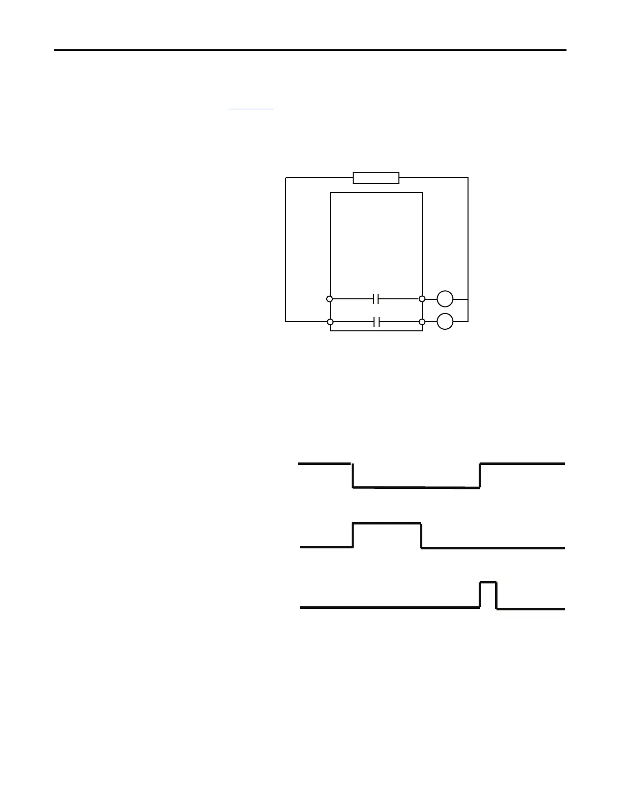
Figure 208 is a wiring diagram of a Two-speed Starter with Output Relay 0 and
Output Relay 1 configured as control relays. Both Output Relay 0 and Output
Relay 1 go to an open state when there is a trip event.
Figure 208 - Two-Speed Starter (Custom) Wiring Diagram
DeviceLogix Program
The last saved DeviceLogix program is executed in the E300 on power-up or
when Operating Mode (Parameter 195) is set to a value of 53.
Timing Diagram
Figure 209 - Two-Speed Starter (Custom) Timing Diagram
Monitor Operating Mode
The E300 relay’s monitor-based operating mode allows you to disable all
protection features of the E300 relay. You can use the E300 relay as a monitoring
device to report current, voltage, power, and energy information.
There is one monitor based operating mode – Custom.
R13 R14
Relay 0
Run Slow
E300
Control Power
R03 R04
Relay 0
Run Fast
Trip Relay
Trip Reset
Device
Status0.Trip
Present

 Loading...


