EasyManuals Logo

Allen-Bradley E300 User Manual

Allen-Bradley E300
736 pages
To Next Page IconTo Next Page
To Previous Page IconTo Previous Page
Page #32 background image
32 Rockwell Automation Publication 193-UM015E-EN-P - October 2015
Chapter 2 Installation and Wiring
Figure 10 - Expansion Bus Digital and Analog I/O Modules and Power Supply
Expansion Bus Operator
Station Installation
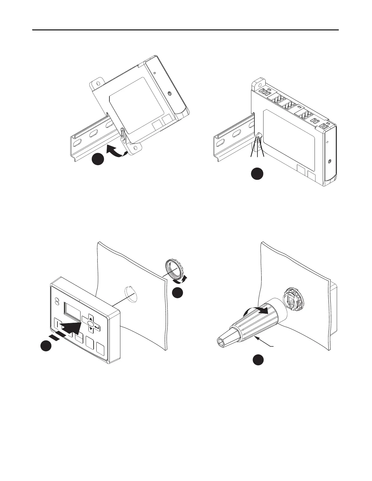
Figure 11 - Expansion Bus Operator Station
Expansion Bus Network
Installation
The E300 relay supports up to (4) Expansion Digital I/O modules, (4)
Expansion Analog I/O modules, and (1) Operation Station. The E300 Base
Relay can supply enough power for (1) Expansion Digital I/O module and (1)
Operator Station. Any other combination of E300relay
Expansion Bus
peripherals requires an Expansion Bus Power Supply, which connects as the first
module on the Expansion Bus.
1
2
Click
2
1
1.7 N
.
m
(15 lb-in)
0
RESET
SELECT
ESC
REMOTE
LOC AL
800F-AW2
3

Table of Contents

Other manuals for Allen-Bradley E300

Questions and Answers:

Question and Answer IconNeed help?

Do you have a question about the Allen-Bradley E300 and is the answer not in the manual?

Allen-Bradley E300 Specifications

General IconGeneral
TypeElectronic Overload Relay
MountingDIN Rail or Panel Mount
Protection ClassIP20
Voltage Range24…690 V AC/DC
Communication OptionsEtherNet/IP, DeviceNet
ProtectionOverload, phase loss, ground fault
Operating Temperature-20°C to 60°C

Related product manuals