Rockwell Automation Publication 193-UM015E-EN-P - October 2015 443
Protective Trip and Warning Functions Chapter 6
Analog-based Protection
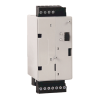
The E300 relay’s Analog I/O Expansion Modules scan up to three analog signals
per module. This information can be used to trigger an over analog level Trip or
Warning. The analog-based protection features can be used with the following
analog applications:
• Monitoring motor winding and bearing temperatures that are measured by
RTD sensors
• Monitoring liquid, air, or steam flow
• Monitoring temperature
• Monitoring weight
• Monitoring levels
• Monitoring a potentiometer
• Monitoring PTC or NTC thermistor sensors
A
n
a
log Trip Enable (Parameter 187) and Analog Warning Enable (Parameter
193) are us
ed to enable the respective analog-based protective trip and warning
functions.
Table 377 - Analog Trip Enable (Parameter 187)
Table 378 - Analog Warning Enable (Parameter 193)
Bit
1514131211109876543210 Function
XAnalog Module 1 - Input Channel 00 Trip
XAnalog Module 1 - Input Channel 01 Trip
XAnalog Module 1 - Input Channel 02 Trip
XAnalog Module 2 - Input Channel 00 Trip
XAnalog Module 2 - Input Channel 01 Trip
XAnalog Module 2 - Input Channel 02 Trip
XAnalog Module 3 - Input Channel 00 Trip
XAnalog Module 3 - Input Channel 01 Trip
XAnalog Module 3 - Input Channel 02 Trip
XAnalog Module 4 - Input Channel 00 Trip
XAnalog Module 4 - Input Channel 01 Trip
XAnalog Module 4 - Input Channel 02 Trip
Bit
15 14 13 12 11 10 9 8 7 6 5 4 3 2 1 0 Function
XAnalog Module 1 - Input Channel 00 Warning
XAnalog Module 1 - Input Channel 01 Warning
XAnalog Module 1 - Input Channel 02 Warning
XAnalog Module 2 - Input Channel 00 Warning
XAnalog Module 2 - Input Channel 01 Warning
XAnalog Module 2 - Input Channel 02 Warning
X Analog Module 3 - Input Channel 00 Warning
X Analog Module 3 - Input Channel 01 Warning
XAnalog Module 3 - Input Channel 02 Warning
XAnalog Module 4 - Input Channel 00 Warning
XAnalog Module 4 - Input Channel 01 Warning
XAnalog Module 4 - Input Channel 02 Warning

 Loading...


