170 Rockwell Automation Publication 193-UM015E-EN-P - October 2015
Chapter 5 Operating Modes
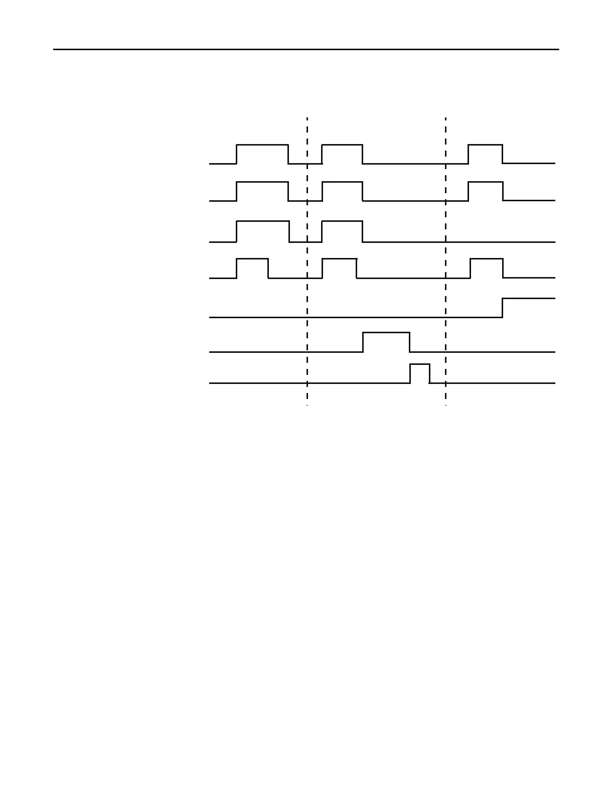
Timing Diagram
Figure 75 - Non-reversing Starter (Network) with Feedback Timing Diagram
Non-reversing Starter (Operator Station)
The E300 relay’s Operating Mode Non-Reversing Starter (Operating Station)
(Parameter 195 = 27) uses the Operator Station’s “I” and “0” keys to control
Relay 0, which controls the contactor coil. These keys are momentary push
buttons, so the non-reversing starter remains energized when you release the “I”
button. The E300 issues a trip or warning event if the E300 Operator Station
disconnects from the base relay.
The reset button of the E300 Operator Station is enabled, and the Local/Remote
yellow LED is illuminated to indicate that the operator station is being used for
local control.
Rules
1. Available for Control Module firmware v5.000 and higher.
2. Output Pt00 Assignment (Parameters 202) must be set to Control Relay.
3. Overload Trip must be enabled in TripEnableI (Parameter 183).
4. Operator Station Trip must be disabled in TripEnableC (Parameter 186).
5. Operator Station Option Match Trip or Warning must be enabled.
Trip Event Feedback Timeout
Feedback
Relay 0
Timer
Feedback
Timeout Trip
Trip Status
Trip Reset
Normal Operation
Run/Stop

 Loading...


