Rockwell Automation Publication 193-UM015E-EN-P - October 2015 171
Operating Modes Chapter 5
• Option Match Trip or must be enabled in TripEnableC
(Parameter 186)
• O
perator Station must be enabled in Mismatch Action
(Parameter 233)
• An
operator station must be selected in Operator Station Type
(Parameter 224)
Or
• O
ption Match Warning must be enabled in WarningEnableC
(Paramete
r 192)
• Operator Station must be disabled in Mismatch Action
(Parameter 233)
• An
operator station must be selected in Operator Station Type
(Parameter 224)
6. Com
munication Fault & Idle Override (Parameter 346) must be enabled.
7. Network Fault Override (Parameter 347) must be enabled.
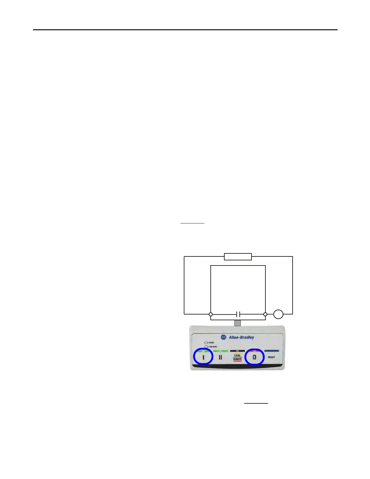
Wiring Diagram
The E300 relay’s Output Relay 0 is wired as a control relay, and it opens when a
trip event occurs. Figure 76
is a wiring diagram of a non-reversing starter with
Output Relay 0 configured as a control relay.
Figure 76 - Non-reversing Starter (Operator Station) Wiring Diagram
DeviceLogix Program
The DeviceLogix program that is shown in Figure 77 is automatically loaded and
enabled in the E300 on power-up or when Operating Mode (Parameter 195) is
set to a value of 27.
R03 R04
Relay 0
Run
E300
Control Power
I- Run 0- Stop

 Loading...


