56 Rockwell Automation Publication 193-UM015E-EN-P - October 2015
Chapter 2 Installation and Wiring
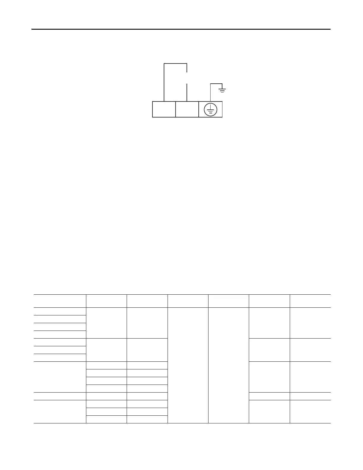
Figure 47 - E300 Expansion Power Supply Wiring Diagram
Grounding
The following grounding recommendations are provided to help ensure EMC
requirements during installation
.
• The earth ground terminal of the E300 relay is a convenience terminal for
the green shield wire of the Cat. No. 193-ECM-ETR. The E300 Control
Module does not make an electrical connection to this terminal.
• Wire the green shield wire of the Cat. No. 193-ECM-ETR into the earth
grou
nd terminal of the E300 control module.
• I
nstallations that employ an external ground fault sensor shall ground the
cable shield
at the sensor with no connection made at the E300 relay.
• The PTC thermistor cable shield shall be grounded at the E300 relay with
no c
onnection made at the opposite end.
Short-Circuit Ratings
The E300 relay is suitable for use on circuits capable of delivering not more than
the RMS symmetrical amperes listed in the following tables.
Table 9 - Standard Fault Short Circuit Ratings per UL60947-4-1 and CSA 22.2 No. EN60947-4-1
Sensing Module Cat. No. Contactor Cat. No. Max. Starter FLC [A]
Max. Available Fault
Current [A]
Max. Voltage [V AC]
Max. RKs non-time
Delay Fuse Size [A]
Max. Listed Circuit
Breaker Size [A]
193-ESM-___-30A-P — — 5000 600 110 110
193-ESM-VIG-30A-CT
193-ESM-___-30A-T
193-ESM-___-30A-E3T
193-ESM-___-60A-P — — 225 225
193-ESM-___-60A-T
193-ESM-___-60A-E3T
193-ESM-___-30A-C23 100-C09 9 90 90
100-C12 12
100-C16 16
100-C23 23
193-ESM-___-30A-C55 100-C30 30 200 200
193-ESM-___-60A-C55 100-C37 37 200 200
100-C43 43
100-C55 55

 Loading...


