Rockwell Automation Publication 193-UM015E-EN-P - October 2015 301
Operating Modes Chapter 5
Timing Diagram
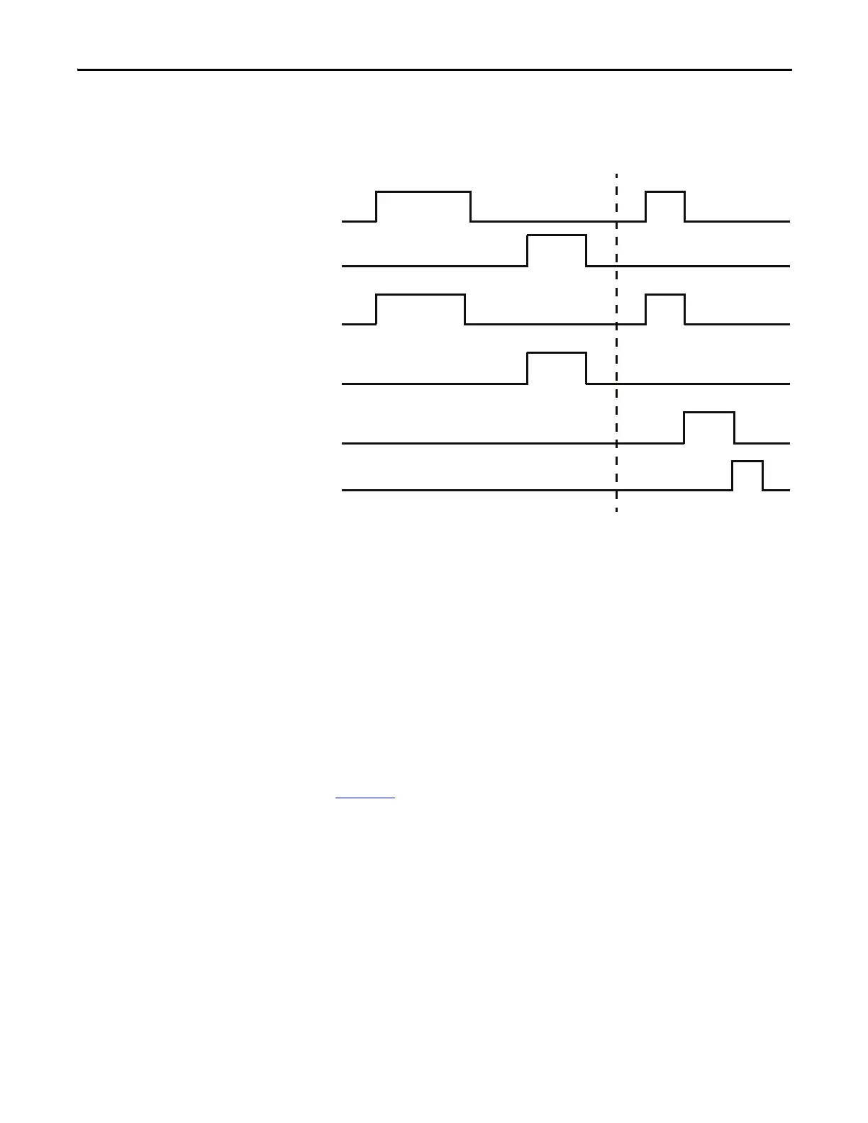
Figure 203 - Two-speed Starter (Network & Local I/O) – Two-wire Control Timing Diagram
Two-speed Starter (Network & Local I/O) – Three-wire Control
The E300 relay’s Operating Mode Two Speed Starter (Network& Operator
Station) (Parameter 195 = 25) in Remote control mode uses network tags
LogicDefinedPt00Data in Output Assembly 144 to control Relay 0, which
controls the high-speed contactor coil, and LogicDefinedPt01Data in Output
Assembly 144 to control Relay 1, which controls the low-speed contactor coil.
Both LogicDefinedPt00Data and LogicDefinedPt01Data are maintained values,
so the two-speed starter remains energized when LogicDefinedPt00Data or
LogicDefinedPt01Data has a value of 1. You can program the appropriate state of
the starter when communication is lost using the Network Communication Fault
and Network Communication Idle parameters (Parameters 569 – 573) described
in Chapter 4
.
Local control mode uses a normally open momentary push button in Input 0 to
energize Output Relay 0, which controls the high-speed contactor coil. A
normally open momentary push button in Input 1 is used to energize Output
Relay 1, which controls the low-speed contactor coil. A normally closed push
button in Input 2 is used to de-energize Output Relay 0 and Output Relay 1.
Both Input 0, Input 1, and Input 2 are momentary signals, so the two-speed
starter only energizes if Input 2 is active and Input 0 or Input 1 is momentarily
active.
Input 3 is used to select between Local and Remote control mode. Activate Input
3 to select Remote control mode. De-activate Input 3 to select Local control
mode.
Trip Event
Trip Status
Trip Reset
Slow (Relay 1)
Fast (Relay 0)
Run Fast
Run Slow

 Loading...


