302 Rockwell Automation Publication 193-UM015E-EN-P - October 2015
Chapter 5 Operating Modes
InterlockDelay (Parameter 215) defines the minimum time delay when switching
direction.
The reset button of the E300 Operator Station is enabled for this operating
mode.
Rules
1. Available for Control Module firmware v5.000 and higher.
2. Four digital inputs must be available on the Control Module
3. Output Pt00 Assignment (Parameters 202) must be set to Control Relay.
4. Output Pt01 Assignment (Parameters 203) must be set to Control Relay.
5. Overload Trip must be enabled in TripEnableI (Parameter 183).
6. Communication Fault & Idle Override (Parameter 346) must be enabled.
7. Network Fault Override (Parameter 347) must be enabled.
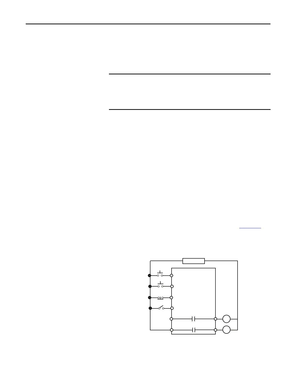
Wiring Diagram
The E300 relay’s Output Relay 0 and Output Relay 1 are wired as a control relays
in which the relay is controlled by the communication network or Input 0, Input
1, and Input 2. Both output relays open when a trip event occurs. Figure 204
is a
wiring diagram of a two-speed starter with Output Relay 0 and Output Relay 1
configured as control relays.
Figure 204 - Two-speed Starter (Network & Local I/O) – Three-wire Control Wiring Diagram
The Two-speed Starter (Network & Operator Station) operating mode uses the
value in network tag LogicDefinedPt00Data or LogicDefinedPt01Data to control
the starter. When communication is restored between an automation
controller and the E300, the starter energizes if the value in
LogicDefinedPt00Data or LogicDefinedPt01Data is set to 1.
R13 R14
Relay 0
Run Slow
E300
Control Power
R03 R04
Relay 0
Run Fast
Stop
IN 2
IN 1
Run Slow
IN 0
Run Fast
IN 3Local Inputs/
Controller

 Loading...


