164 Rockwell Automation Publication 193-UM015E-EN-P - October 2015
Chapter 5 Operating Modes
Figure 68 - Control Relay Wiring Diagram
DeviceLogix Program
The last saved DeviceLogix program is executed in the E300 on power-up or
when Operating Mode (Parameter 195) is set to a value of 49.
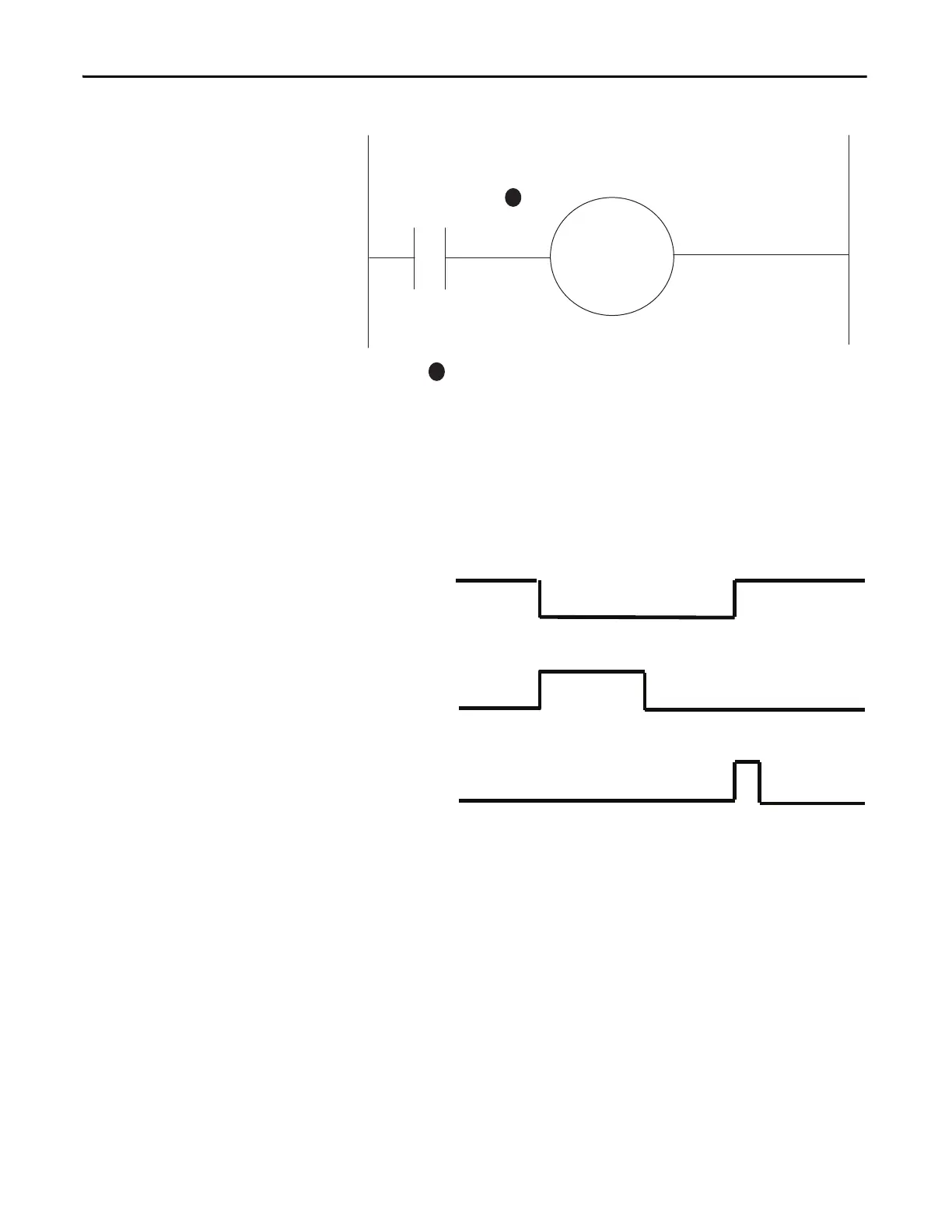
Timing Diagram
Figure 69 - Overload (Custom) Timing Diagram
Non-reversing Starter
Operating Modes
The non-reversing starter-based operating modes of the E300 relay provide the
control logic for a non-reversing full voltage starter. A normally open control
relay controls the contactor coil. When a trip event occurs, the control relay
remains open until the E300 receives a trip reset command. There are 15 non-
reversing starter-based operating modes to choose from:
• Network
• Network with Feedback
• Operator Station
• Operator Station with Feedback
• Local I/O – Two-wire Control
• Local I/O with Feedback – Two-wire Control
• Local I/O – Three-wire Control
Relay 0
Configured as a
Control Relay
R03 R04
A1
A2
M
1
1
Contact shown with supply voltage applied.
Trip Relay
Trip Reset
Device
Status0.Trip
Present

 Loading...


