Rockwell Automation Publication 193-UM015E-EN-P - October 2015 163
Operating Modes Chapter 5
normally closed trip relay or a normally open control relay. The Overload
(Custom) operating mode is used for applications that want customized
DeviceLogix programs. This operating mode requires minimal configuration
rules.
Rules
1. Available for Control Module firmware v5.000 and higher.
2. Set any of the Output Ptxx Assignments (Parameters 202…204) to Trip
Relay
or Control Relay.
3. O
verload Trip must be enabled in TripEnableI (Parameter 183).
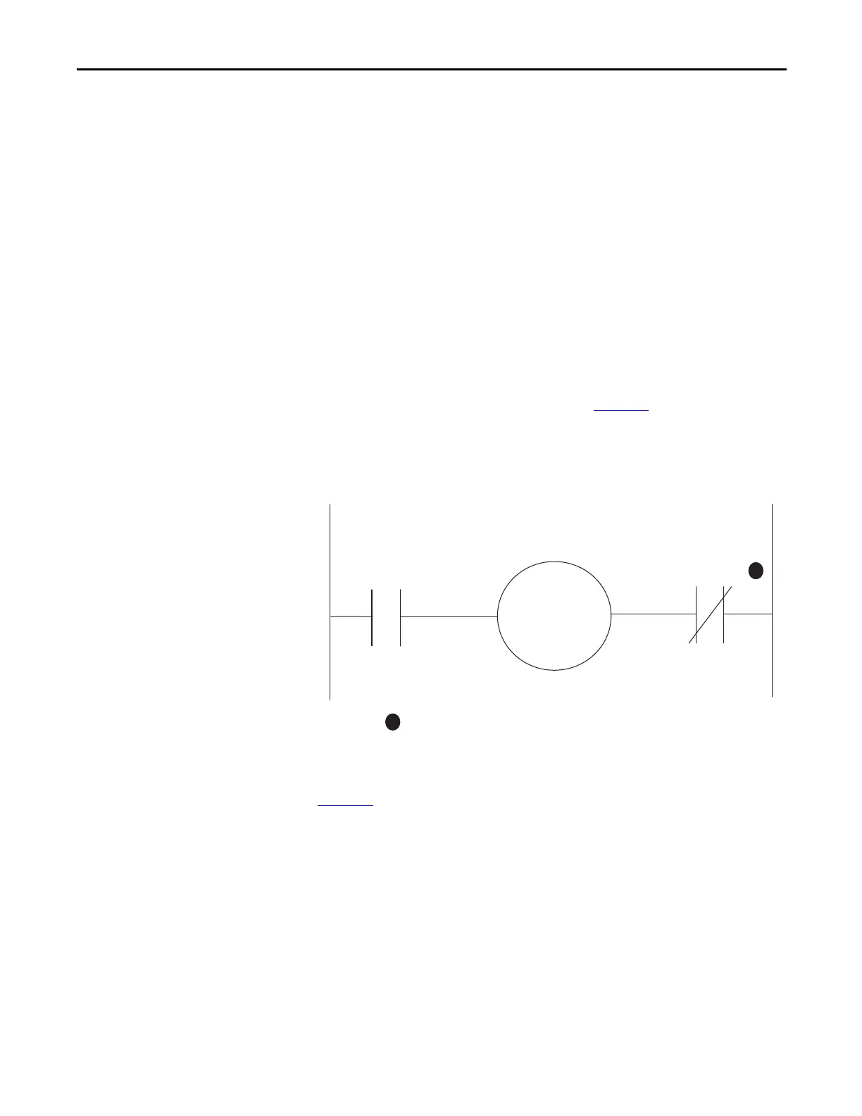
Wiring Diagram
The E300 relay is wired as a traditional overload relay with one of the output
relays configured as a normally closed trip relay. Figure 67
is a wiring diagram of a
non-reversing starter. Relay 0 is configured as a trip relay, and Relay 1 is
configured as a normally open control relay, which receives commands from an
automation controller to energize the contactor coil.
Figure 67 - Trip Relay Wiring Diagram
The E300 relay can also be wired as a control relay so that the relay that is
controlled by the communication network opens when a trip event occurs.
Figure 68
is a wiring diagram of a non-reversing starter with Relay 0 configured as
a control relay. Relay 0 receives control commands from an automation controller
to energize or de-energize the contactor coil. Relay 0 also goes to an open state
when there is a trip event.
Relay 1
Relay 0
Configured as a
Trip Relay
R13 R14
A1
A2
M
R03
R04
1
1
Contact shown with supply voltage applied.

 Loading...


