Rockwell Automation Publication 193-UM015E-EN-P - October 2015 327
Protective Trip and Warning Functions Chapter 6
When the ground fault warning conditions are satisfied, the:
• TRIP/WARN LED status indicator flashes a yellow 3-short blink pattern
• Bit 2 in Current Warning Status (Parameter 10) sets to 1
• Bit 1 of Device Status 0 (Parameter 20) sets to 1
• Any relay outputs configured as a Warning Alarm close
Ground Fault Warning Level
Ground Fault Warning Level (Parameter 246) allows you to define the ground
fault current at which the E300 relay indicates a warning and is adjustable from
0.20…5.00 A.
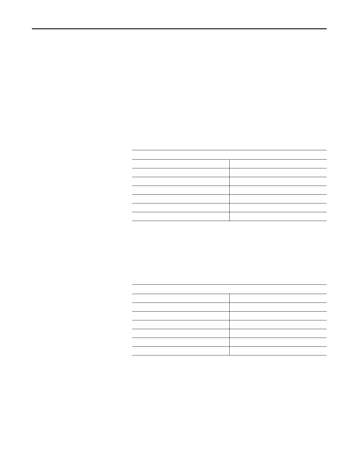
Table 246 - Ground Fault Warning Level (Parameter 246)
Ground Fault Warning Delay
Ground Fault Warning Delay (Parameter 245) allows you to define the time
period (adjustable from 0.0…25.0 s) for which a ground fault condition must be
present before a warning occurs.
Table 247 - Ground Fault Warning Delay (Parameter 245)
Stall Protection
A motor stalls when its inrush current lasts for a longer than normal period of
time during its starting sequence. As a result, the motor heats up rapidly and
reaches the temperature limit of its insulation. Rapid stall detection during the
starting sequence can extend the motor’s life, and minimize potential damage and
loss of production. The E300 relay can monitor for this condition with its Stall
Ground Fault Warning Level (Parameter 246)
Default Value 2.00
Minimum Value 0.20
Maximum Value 5.00
Parameter Type UINT
Size (Bytes) 2
Scaling Factor 100
Units Amps
Ground Fault Warning Delay (Parameter 245)
Default Value 0.0
Minimum Value 0.0
Maximum Value 25.00
Parameter Type USINT
Size (Bytes) 1
Scaling Factor 10
Units Seconds

 Loading...


