B-26
Cisco Security Appliance Command Line Configuration Guide
OL-10088-01
Appendix B Sample Configurations
Example 10: Cable-Based Active/Standby Failover (Transparent Mode)
Example 10: Cable-Based Active/Standby Failover (Transparent
Mode)
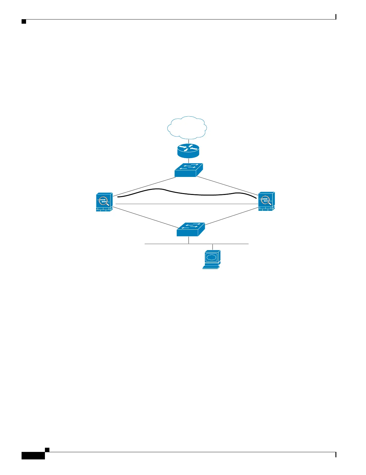
Figure B-6 shows the network diagram for a transparent mode failover configuration using a serial
Failover cable. This configuration is only available on the PIX 500 series security appliance.
Figure B-9 Transparent Mode Cable-Based Failover Configuration
The following are the typical commands in a cable-based, transparent firewall failover configuration.
enable password myenablepassword
passwd mypassword
hostname pixfirewall
asdm image flash:/asdm.bin
boot system flash:/image.bin
firewall transparent
interface Ethernet0
speed 100
duplex full
nameif outside
security-level 0
no shutdown
interface Ethernet1
speed 100
duplex full
nameif inside
security-level 100
no shutdown
interface Ethernet3
description STATE Failover Interface
telnet 192.168.2.45 255.255.255.255 mgmt
access-list acl_in permit tcp any host 209.165.201.5 eq 80
access-group acl_in in interface outside
209.164.201.4
192.168.253.1
192.168.253.2
209.164.201.5
209.165.201.1
209.165.201.2
Switch
Switch
state
Serial Failover Cable
Outside
inside
Primary Unit
Secondary Unit
Web Server
153888
Internet
 Loading...


