Parameter
structure
Keypad and
format
Advanced
parameter
descriptions
Serial comms
5.9
Menu
8:
Digital
I/O
The drive has nine digital I/O terminals (T24 to T29, two relays and an enable input) and two buttons. Each input has the same parameter structure.
The digital inputs are sampled every 4 ms, except when inputs are routed to the limit switch Pr
6.35
and Pr
6.36
when the sample time is reduced to
250 µs. The digital input hardware introduces a further 100 µs delay. The digital outputs are updated every 4 ms. Any changes to the source/
destination parameters only become effective after a drive reset is activated.
I/O
Sample
rate
Function
T24 to T26
4 ms
Digital input or output
T27 to T29
4 ms
Digital input
Relay
Background
Relay 2
Background
Buttons
TBD
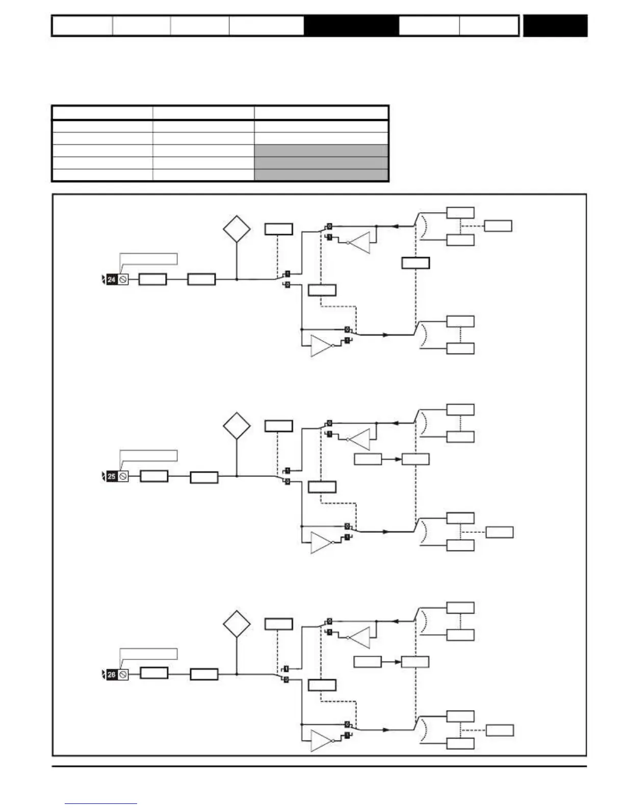
Figure
5-24
Menu
8
logic
diagram
T24 digital
I/O 1 state
8.01
T24 output
select
8.31
??.??
At
speed
10.06
x(-1)
??.??
T24 digital I/O 1
8.29
I/O polarity
select
8.30
Open collector
output
T24 digital
I/O 1 source/
destination
8.11
T24
digital
I/O 1 invert
8.21
Any
bit
parameter
Any
unprotected
bit
parameter
x(-1)
??.??
??.??
T25 digital
I/O 2 state
T25 output
select
Any
bit
parameter
??.??
8.02
8.32
x(-1)
??.??
T25 digital I/O 2
8.29
I/O polarity
select
8.30
Open collector
output
6.04
logic select
T25 digital
I/O 2 invert
8.22
T25 digital
I/O 2 source/
destination
Any
unprotected
bit
parameter
??.??
Drive reset
10.33
x(-1)
??.??
T26 digital
I/O 3 state
T26 output
select
Any bit
parameter
??.??
8.03
8.33
x(-1)
??.??
T26 digital I/O 3
8.29
I/O polarity
select
8.30
Open collector
output
6.04
logic select
T26 digital
I/O 3 invert
8.23
T26 digital
I/O 3 source/
destination
Any
unprotected
bit
parameter
??.??
Run forward
6.30
x(-1)
??.??
Mentor MP Advanced User Guide
115
Issue Number: 4
www.onxcontrol.com
 Loading...


