Parameter
Keypad and
Advanced
parameter
descriptions
Serial comms
Menu
5
= RC
2
C
R
Temp
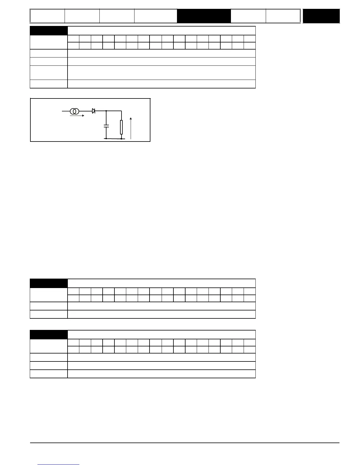
The temperature of the field as a percentage of maximum temperature, with a constant current magnitude of I and constant value of field rated current
(set by Pr
5.70
{
SE10,
0.31
} or Pr
21.24
) after time t is given by
Temp = [I
2
/ (1.20*Field rated current)
2
] (1 - e
-t/
) x 100 %
This assumes that the maximum allowed field temperature is produced by 1.20 x field rated current and that
is the thermal filter of the point in the
motor that reaches it maximum allowed temperature first.
is defined by Pr
5.81
. The estimated motor temperature is given by Pr
5.82
as a percent-
age of maximum temperature. If the Pr
5.81
has a value between 0.0 and 1.0 the thermal filter is taken as 1.0.
When the estimated temperature reaches 100 % the drive stops the motor and then trips on F.OVL.
The time for some action to be taken by the drive from cold with constant field current is given by:
T
trip
=
-(Pr
5.81
)
x
ln(1
-
(1.20
x
Pr
5.70
{
SE10,
0.31
}
/
Pr
5.56
{
di09,
0.44
})
2
)
Alternatively the thermal filter can be calculated from the trip time with a given current from
Pr
5.81
=
-T
trip
/
ln(1
-
(1.20
/
Overload)
2
)
For example, if the drive should trip after supplying 125 % overload for 60 seconds then
Pr
5.81
= -60 / ln(1 - (1.20 / 1.25)
2
) = 24
The thermal model temperature accumulator is reset to zero at power-up and accumulates the temperature of the field while the drive remains pow-
ered-up. Each time Pr
11.45
is changed to select a new motor, or the rated current defined by Pr
5.70
{
SE10,
0.31
} or Pr
21.24
(depending on the
motor selected) is altered, the accumulator is reset to zero.
of operation can be achieved using a 2Q drive and an external field controller. The flux in the field cannot be reduced until the motor has stopped. The
time taken for the motor direction to change, will depend on how quickly the field flux can be reversed. Figure 5-18 and Figure
illustrate the sequence
of events during a forward to reverse and reverse to forward change of direction.
Mentor MP Advanced User Guide
93
Issue Number: 4
www.onxcontrol.com
5.81
 Loading...


