Parameter
structure
Keypad and
description format
Advanced
parameter
descriptions
Serial comms
Menu
5
Figure
5-11
6
Pulse
parallel
operation
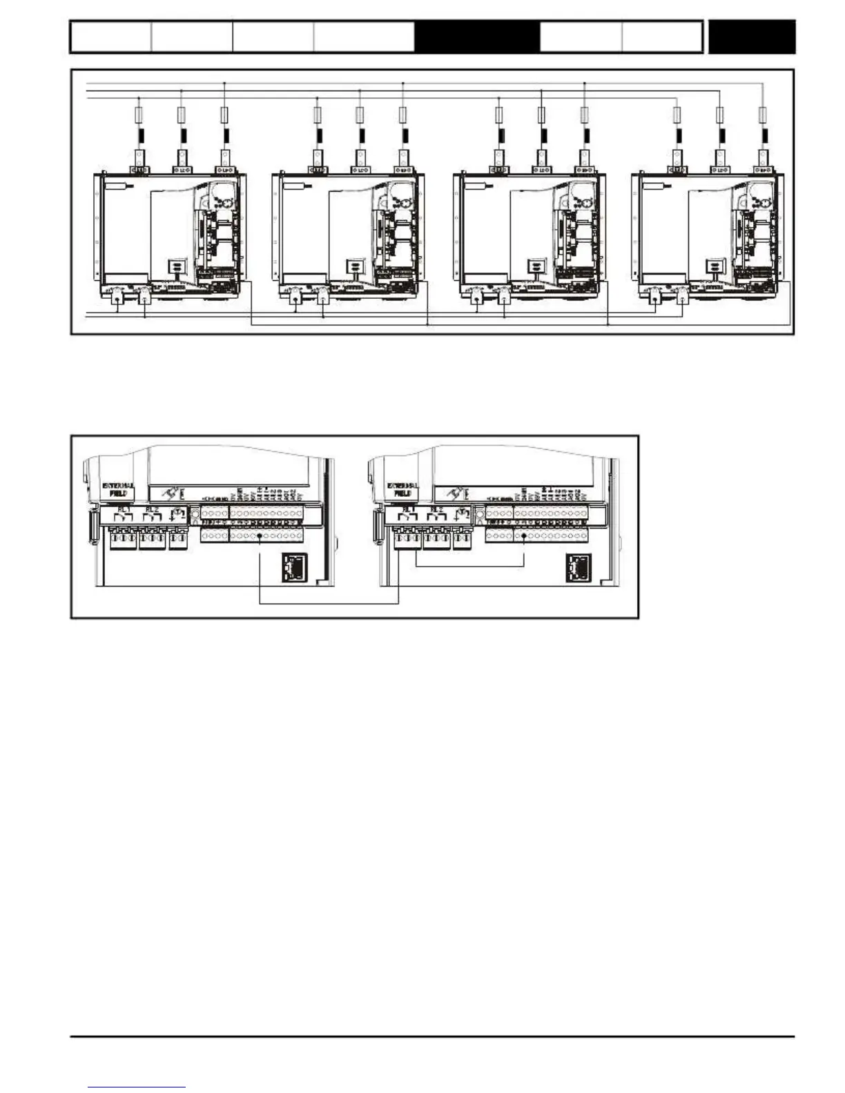
4
drives
L3
L2
L1
Fuses*
Choke
/
inductor
Fuses*
Choke
/
inductor
Fuses*
Choke
/
inductor
Fuses*
Choke
/
inductor
Master
drive
Slave
drive
Slave
drive
RJ
45
Slave
drive
A1
A2
RJ
45
parallel
comms
*For fuse information please refer to section 4.6 in the Mentor MP User Guide.
Master
Drive
in
6
pulse
parallel
system
Slave Healthy
The master drive must know the state of health of the slave (or slaves), in a 6 pulse parallel system. This can be achieved using digital IO or a
communication module. Where there are multiple slave drives, the master can be setup to use 1 bit to check the health of the slave or multiple bits.
Figure
5-12
Single
Slave
Master
Slave
51
52
53
NC
Set Pr
8.22
to Pr
5.45
.
25
RJ
45
parallel
comms
51
52
53
NC
22
RJ
45
parallel
comms
Mentor MP Advanced User Guide
83
Issue Number: 4
www.onxcontrol.com
 Loading...


