structure
Keypad and
format
Advanced
parameter
descriptions
Serial comms
Rigid
position
control
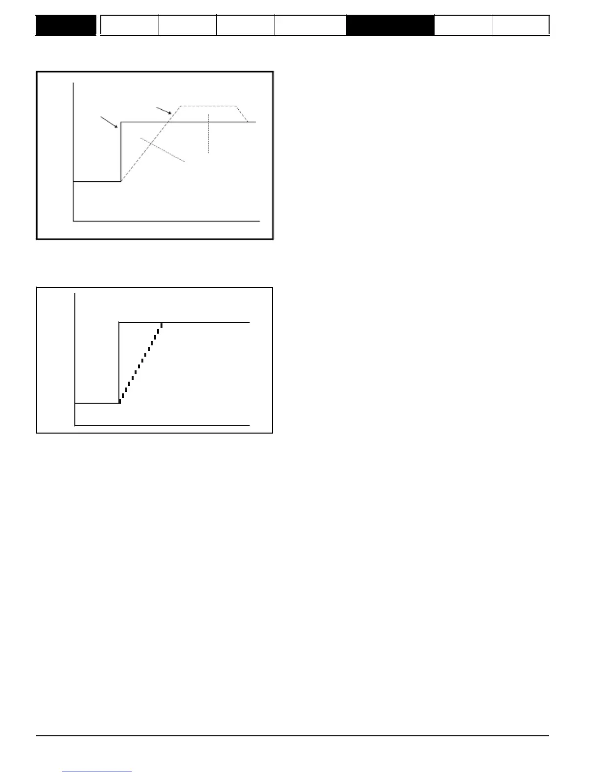
In rigid position control the position error is always accumulated. This means that, if for example, the slave shaft is slowed down due to excessive
load, the target position will eventually be recovered by running at a higher speed when the load is removed.
Speed
Actual
Reference
Equal Areas
t
Non-rigid
position
control
In non-rigid position control the position loop is only active when the 'At Speed' condition is met (see Pr
3.06
on page 44). This allows slippage to
occur while the speed error is high.
Speed
Reference
Actual
Velocity
feed
forward
The position controller can generate a velocity feed forward value from the speed of the reference encoder. The feed-forward value is passed to menu
1, and so ramps may be included if required. Because the position controller only has a proportional gain, it is necessary to use velocity feed-forward
to prevent a constant position error that would be proportional to the speed of the reference position.
If for any reason the user wishes to provide the velocity feed forward from a source other than the reference position, the feed forward system can be
made inactive, i.e. Pr
13.10
= 2 or 4. The external feed forward can be provided via Menu 1 from any of the speed references. However, if the feed
forward level is not correct a constant position error will exist.
Relative
jogging
If relative jogging is enabled the feedback position can be made to move relative to the reference position at the speed defined by Pr
13.17
.
Orientation
If Pr
13.10
is 5 the drive orientates the motor following a stop command. If hold zero speed is enabled (Pr
6.08
= 1) the drive remains in position
control when orientation is complete and holds the orientation position. If hold zero speed is not enabled the drive is disabled when orientation is
complete.
If Pr
13.10
is 6 the drive orientates the motor following a stop command and whenever the drive is enabled provided that hold zero speed is enabled
(Pr
6.08
= 1). This ensures that the spindle is always held in the same position following the drive being enabled.
When orientating from a stop command the drive goes through the following sequence:
1.
The motor is decelerated or accelerated to the speed limit programmed in Pr
13.12
, using ramps if these are enabled, in the direction the motor
was previously running.
2.
When the ramp output reaches the speed set in Pr
13.12
, ramps are disabled and the motor continues to rotate until the position is found to be
close to the target position (i.e. within 1/32 of a revolution). At this point the speed demand is set to 0 and the position loop is closed.
3.
When the position is within the window defined by Pr
13.14
, the orientation complete indication is given in Pr
13.15
.
The stop mode selected by Pr
6.01
has no effect if orientation is enabled.
176
Mentor MP Advanced User Guide
www.onxcontrol.com
Issue Number: 4
 Loading...


