EasyManuals Logo
Home>Emerson>DC Drives>Mentor MP

Emerson Mentor MP User Manual

Emerson Mentor MP
222 pages
To Next Page IconTo Next Page
To Previous Page IconTo Previous Page
Page #213 background imageLoading...
Page #213 background image
Parameter structure
Keypad and display
Parameter x.00
Parameter
description
protocol
Performance
Table
6
-
4
Slave
FC23
Read/Write
multiple
Table
6
-
7
Master
request
Table
6
-
5
Master
request
Table
6
-
8
Slave
response
Ta
ble
6
-
6
Slave
6.2.7
Extended
data
types
format
Advanced parameter
descriptions
Serial
comms
Writes and reads two contiguous arrays of registers. The slave imposes
an upper limit on the number of registers which can be written. If this is
exceeded the slave will discard the request and the master will time out.
FC16
Write
multiple
Writes a contiguous array of registers. The slave imposes an upper limit
on the number of registers which can be written. If this is exceeded the
slave will discard the request and the master will time out.
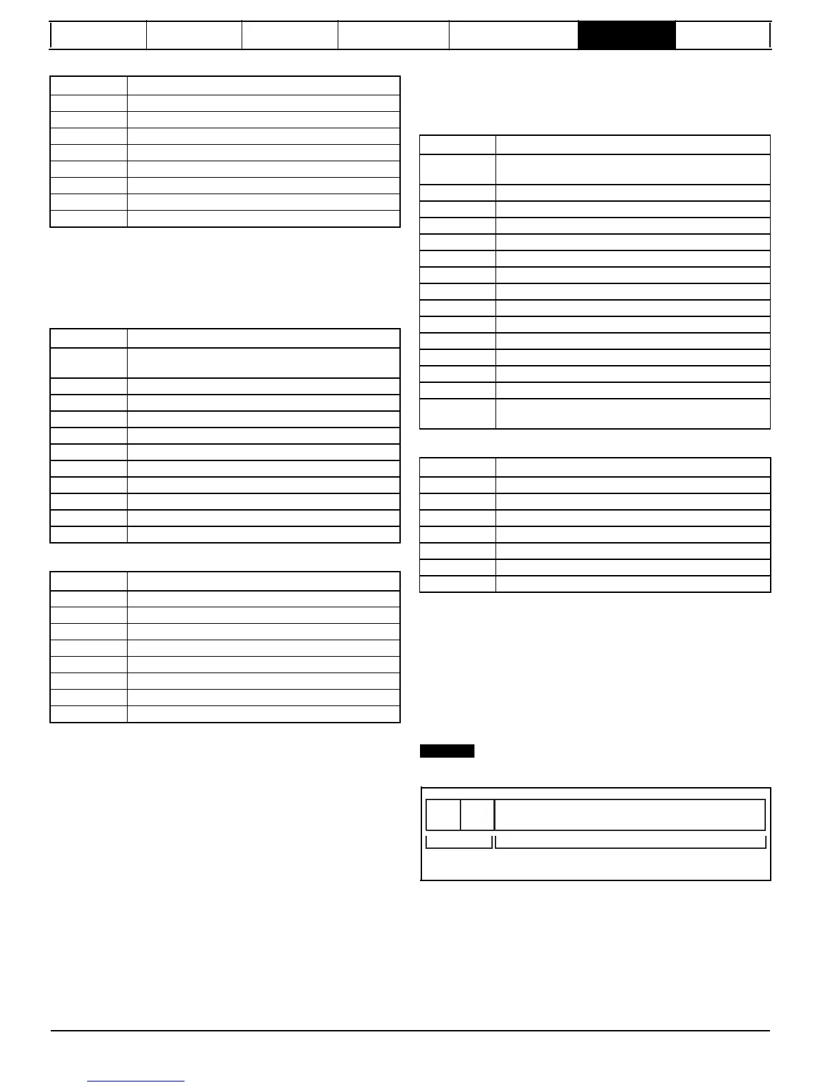
Standard MODBUS registers are 16bit and the standard mapping maps
a single #X.Y parameter to a single MODBUS register. To support 32bit
data types (integer and float) the MODBUS multiple read and write
services are used to transfer a contiguous array of 16bit registers.
Slave devices typically contain a mixed set of 16bit and 32bit registers.
To permit the master to select the desired 16bit or 32bit access the top
two bits of the register address are used to indicate the selected data
type.
NOTE
The selection is applied for the whole block access.
bit 15
TYP1
bit 14
TYP0
bits 0 - 13
Type select
Parameter address
X x 100+Y-1
208
Mentor MP Advanced User Guide
www.onxcontrol.com
Issue Number: 4
Byte
Description
0
Slave
node
address
1
through
247
0 is global
1
Function
code
0x17
2
Start
register
address
to
read
MSB
3
Start
register
address
to
read
LSB
4
Number
of
16bit
registers
to
read
MSB
5
Number
of
16bit
registers
to
read
LSB
6
Start
register
address
to
write
MSB
7
Start
register
address
to
write
LSB
8
Number
of
16bit
registers
to
write
MSB
9
Number
of
16bit
registers
to
write
LSB
10
Length
of
register
data
to
write
(in
bytes)
11
Register
data
0
MSB
12
Register
data
0
LSB
11+byte
count
CRC
LSB
12+byte
count
CRC MSB
Byte
Description
0
Slave
node
address
1
through
247,
0 is global
1
Function
code
0x10
2
Start
register
address
MSB
3
Start
register
address
LSB
4
Number
of
16bit
registers
MSB
5
Number
of
16bit
registers
LSB
6
Length
of
register
data
to
write
(in
bytes)
7
Register
data
0
MSB
8
Register
data
0
LSB
7+byte
count
CRC
LSB
8+byte
count
CRC
MSB
Byte
Description
0
Slave
source
node
address
1
Function
code
0x06
2
Register
address
MSB
3
Register
address
LSB
4
Register
data
MSB
5
Register
data
LSB
6
CRC
LSB
7
CRC
MSB
Byte
Description
0
Slave
source
node
address
1
Function
code
0x10
2
Start
register
address
MSB
3
Start
register
address
LSB
4
Number
of
16bit
registers
written
MSB
5
Number
of
16bit
registers
written
LSB
6
CRC
LSB
7
CRC
MSB
Byte
Description
0
Slave
source
node
address
1
Function
code
0x17
2
Length
of
register
data
in
read
block
(in
bytes)
3
Register
data
0
MSB
4
Register
data
0
LSB
3+byte
count
CRC
LSB
4+byte
count
CRC
MSB

Table of Contents

Other manuals for Emerson Mentor MP

Questions and Answers:

Question and Answer IconNeed help?

Do you have a question about the Emerson Mentor MP and is the answer not in the manual?

Emerson Mentor MP Specifications

General IconGeneral
BrandEmerson
ModelMentor MP
CategoryDC Drives
LanguageEnglish

Related product manuals