structure
Keypad and
format
Advanced
parameter
descriptions
Serial comms
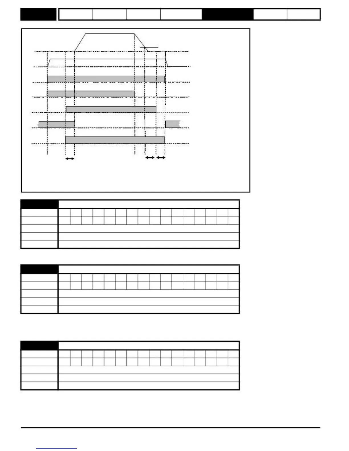
Figure
5-32
Brake
sequence
Pr
12.45
Speed threshold
Pr
3.02
Motor Speed
Torque present
Pr
10.02
Drive active
Pr
1.11
Reference on
Pr
12.40
Brake release
Pr
2.03
Ramp hold
Pr
13.10
Position control mode
Pr
6.08
Hold zero speed
1
2
3
4
5
Pr
12.47
Pr
12.46
Pr
12.48
1. Wait for armature current and fully fluxed machine
2. Post-brake release delay
3. Wait for speed threshold
4. Wait for brake apply speed delay
5. Brake apply delay
12.43
Torque
proving
threshold
Coding
Bit
SP
FI
DE
Txt
VM
DP
ND
RA
NC
NV
PT
US
RW
BU
PS
1
1
1
Range
0 to 150 %
Default
10
Update
rate
Background read
This parameter should be set to a level that is required to hold a load when the brake is released.
12.45
Brake
apply
speed
Coding
Bit
SP
FI
DE
Txt
VM
DP
ND
RA
NC
NV
PT
US
RW
BU
PS
1
1
1
Range
0 to 200 rpm
Default
5 rpm
Update
rate
Background read
When stopping, the drive reference can be removed (i.e. Pr
1.11
= 0), but the brake will remain energized (open), until the motor has remained at a
speed below the brake apply speed for the delay defined by Pr
12.46
. The delay prevents rapid activation and de-activation of the brake when fine
control of a motor is required close to zero speed.
12.46
Brake
apply
speed
delay
Coding
Bit
SP
FI
DE
Txt
VM
DP
ND
RA
NC
NV
PT
US
RW
BU
PS
1
1
1
Range
0.0 to 25.0 s
Default
1.0 s
Update
rate
Background read
See Pr
12.45
for
more
information
.
168
Mentor MP Advanced User Guide
www.onxcontrol.com
Issue Number: 4
 Loading...


