Parameter
structure
Keypad and
description format
Advanced
parameter
descriptions
Serial comms
Menu
5
Setup
Sequence
Table
5-3
Parallel
12
Pulse,
2Q
Using
I/O
Connections
Master
Setting
Description
Slave
Setting
Description
Pr
7.19
= 4.04
Analog output 1 to output current demand
Pr
7.14
= 4.08
Analog input 2 to be torque input
Pr
5.43
= 1
Armature mode to parallel 12 pulse
Pr
4.11
= 1
Select torque mode
Pr
5.43
= 1
Armature mode to parallel 12 pulse
Pr
10.52
= 168
Mask field loss trip
Pr
10.62
= Off
Mask field loss trip
Table
5-4
Parallel
12
Pulse,
4Q
Using
IO
Connections
Master
Setting
Description
Slave
Setting
Description
Pr
7.19
= 4.04
Analog output 1 to output current demand
Pr
7.14
= 4.08
Analog input 2 to be torque input
Pr
8.21
= 5.44
Digital output to master bridge selected
Pr
8.21
= 5.44
Digital output to master bridge selected
Pr
8.22
= 5.45
Digital input 2 to slave bridge selected
Pr
8.22
= 5.45
Digital input 2 to slave bridge selected
Pr
5.43
= 2
Armature mode to parallel 12 pulse with bridge lockout
Pr
4.11
= 1
Select torque mode
Pr
10.52
= 168
Mask field loss trip
Pr
10.62
= Off
Mask field loss trip
Pr
5.43
= 2
Armature mode to parallel 12 pulse with bridge lockout
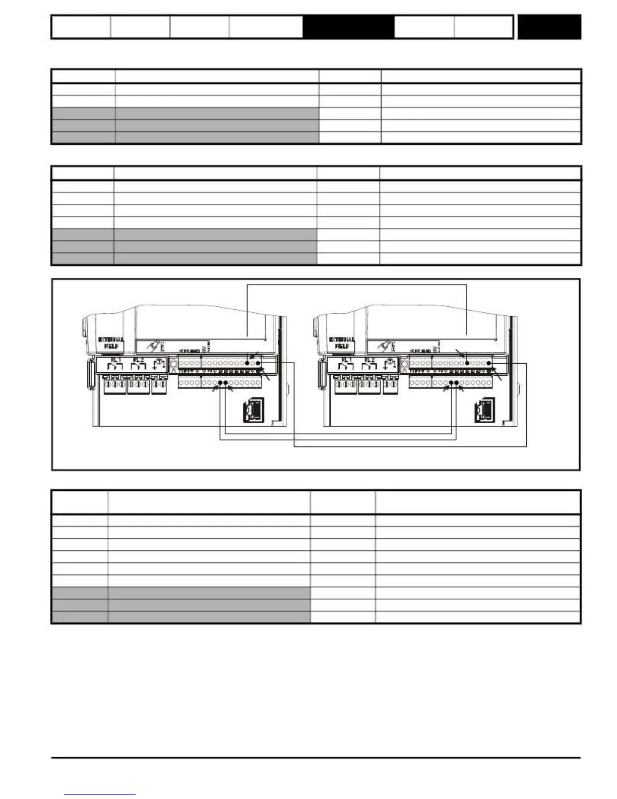
Figure
5-8
Master
Slave
control
connection
detail
for
12
pulse
Analog output
1 (Master)
Master
Slave
T9
T7
0V
0V
T24
T25
T11
T24
T25
T11
NOTE:
Connection to T24 and T25 are only required for 4Q systems.
Table
5-5
Parallel
24
pulse
4Q
Using
I/O
connections
Master
Pr
7.19
= 4.04
Analog output 1 to output current demand
Pr
7.14
= 4.08
Analog input 2 to be torque input
Pr
8.21
= 5.44
Digital output to master bridge selected
Pr
8.21
= 5.44
Digital output to master bridge selected
Pr
8.22
= 5.45
Digital input 2 to slave 1 bridge selected
Pr
8.22
= 5.45
Digital input 2 to slave 1 bridge selected
Pr
8.25
= 5.46
Digital input 5 to slave 2 bridge selected
Pr
8.25
= 5.46
Digital input 5 to slave 2 bridge selected
Pr
8.26
= 5.47
Digital input 6 to slave 3 bridge selected
Pr
8.26
= 5.47
Digital input 6 to slave 3 bridge selected
Pr
5.43
= 3
Armature mode to parallel 24 pulse with bridge lockout
Pr
4.11
= 1
Select torque mode
Pr
10.52
= 168
Mask field loss trip
Pr
10.62
= Off
Mask field loss trip
Pr
5.43
= 3
Armature mode to parallel 24 pulse with bridge lockout
Mentor MP Advanced User Guide
81
Issue Number: 4
www.onxcontrol.com
 Loading...


