Menu
5
Parameter
structure
Keypad and
description format
Advanced
parameter
descriptions
Serial comms
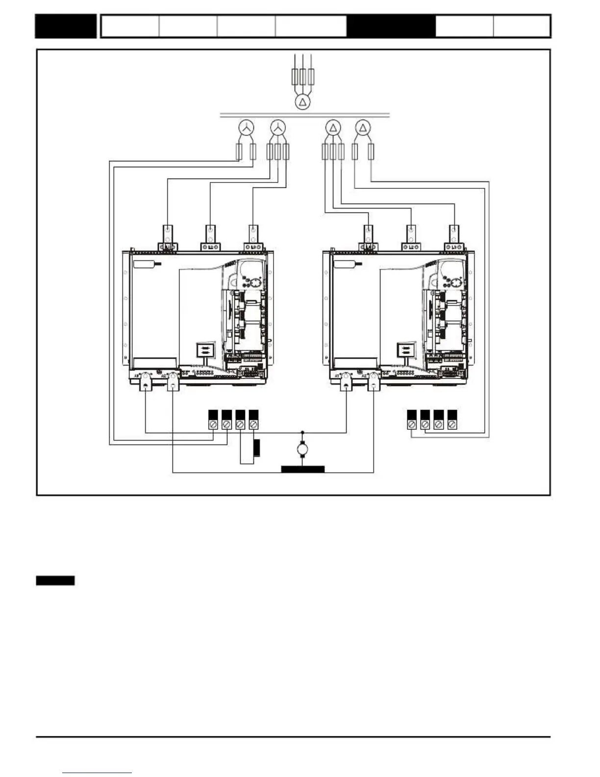
Figure
5-7
Parallel
12
Pulse
Three
phase
transformer
Fuses*
Master
drive
Slave
drive
E1
E3
F+
F-
E1
E3
F+
F-
Motor
field
winding
Motor
armature
Interbridge
reactor
*For fuse information please refer to section 4.6 in the Mentor MP User Guide.
To configure the drives for use in a parallel 12 pulse speed control system, they should be programmed so that the master drive is set up in speed
control mode (Pr
4.11
= 0), and the slave drive is programmed in torque control mode (Pr
4.11
= 1). The final current demand (Pr
4.04
) on the master
drive has to be fed in to the slave drive torque reference (Pr
4.08
). This current demand signal can be transferred between the drives using either an
analog input / output, communication module or by using CT Sync.
Additional bridge interlocking signals are shared between the two modules, when a four quadrant system is required to ensure that the same bridge
on both drives is firing and also that the current has reached zero on both drives before current reversal is attempted.
NOTE
Only terminals relevant to 12 pulse operation have been shown.
80
Mentor MP Advanced User Guide
www.onxcontrol.com
Issue Number: 4
 Loading...


