Parameter
structure
Keypad and
format
Advanced
parameter
descriptions
Serial comms
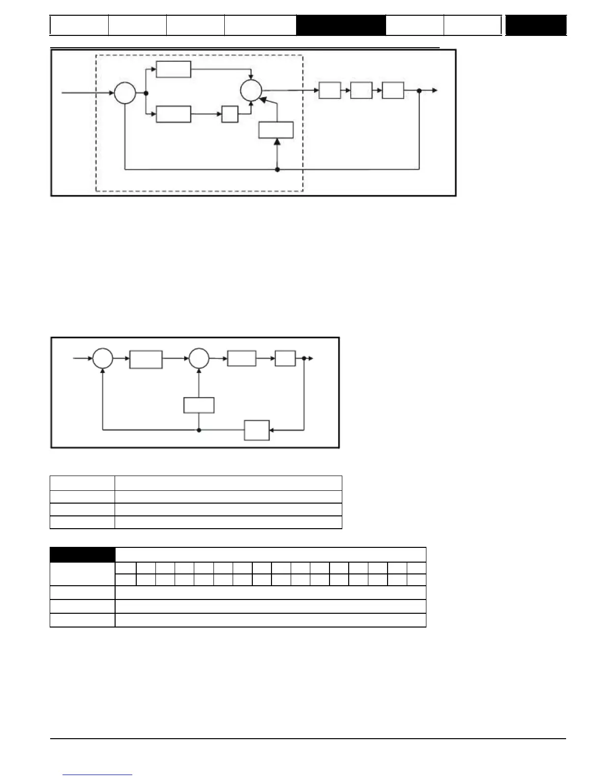
To analyze the performance of the speed controller it may be represented as an s-domain model as shown below.
w*(s)
-1
+
Kp
+
_
Kc
Kt
L(s)
w(s)
rads
-1
_
Ki
1/s
+
Ki.Kd
Speed controller
where:
Kc is the conversion between the speed controller output and torque producing current. A value of unity at the input to this block gives a torque
producing current equivalent to the rated current of the drive. The drive automatically compensates the torque producing current for flux variations in
field weakening, and so Kc can be assumed to have a constant value. Kc is equal to the rated drive current (see Menu 4 for value of Rated drive
current for each drive size).
Kt is the torque constant of the motor (i.e. torque in Nm per amp of torque producing current).
Kt = Motor rated torque / Motor rated current
L(s) is the transfer function of the load.
The s-domain system above may be used to determine the performance of systems with a relatively low bandwidth. However, the real drive system
also includes non-ideal delays due to the torque controller response, and speed measurement and control delays. These delays, which can be
approximated
with
a
simple
unity
gain
transport
delay
(T
delay
)
as
shown
below,
should
be
taken
into
account
for
more
accurate
results.
w*(s)
+
Kp+Ki/s
+
Kc.Kt
L(s)
w(s)
_
_
Ki.Kd
T
delay
The speed controller gains used in previous Mentor II products were in internal drive units. Conversion between the previous internal units and the SI
and constant torque, the drive can calculate the required Kp and Ki gains, provided a value of motor plus load inertia (Pr
3.18
) and the motor torque
per amp (Pr
5.32
) are setup correctly. The calculated values for Kp and Ki are written to Pr
3.10
{
SP01,
0.61
} and Pr
3.11
{
SP02,
0.62
} once per
second when one of these setup methods is selected (i.e. Pr
3.17
= 1 or 2). The values are calculated from a linear model assuming a pure inertia
load, not including unwanted delays in the speed and current controllers. The Kd gain is not affected. If Pr
3.17
is set to 2 automatic gain set up is not
active, but Kp is boosted by a factor of 16.
Mentor MP Advanced User Guide
47
Issue Number: 4
www.onxcontrol.com
3.17
 Loading...


