Parameter
structure
Keypad and
format
Advanced
parameter
descriptions
Serial comms
speed reference is enabled). If the drive is disabled this parameter will show 0.0.
as selected with Pr
3.26
{
Fb01,
0.71
}. Pr
3.02
{
di05,
0.40
} shows the level of the speed feedback selected for the speed controller. Display filtering is
active when this parameter is viewed with one of the drive keypads. The value held in the drive parameter (accessible via comms or an Solutions
Module) does not include this filter, but is a value that is obtained over a sliding 16 ms period to limit the ripple seen in this parameter value. The
speed feedback value includes encoder quantization ripple given by the following equation:
Ripple in Pr
3.02
{
Fb01,
0.71
} = 60 / 16 ms / (ELPR x 4)
The
16
ms
sliding
window
filter
is
always
applied
to
the
value
shown
in
Pr
3.02
{Fb01,
0.71},
but
this
sliding
window
filter
is
not
normally
applied
to
the
actual
speed
feedback
used
by
the
speed
controller
or
the
drive
encoder
reference
system
(Pr
3.43
to
Pr
3.46).
The user may
apply a filter to the speed controller input and the drive encoder reference system input if required by setting Pr
3.42
to the required filter time. The
encoder ripple seen by the speed controller is given by:
Encoder speed ripple = 60 / Filter time / (ELPR x 4)
If Pr
3.42
is set to zero (no filter) the ripple seen by the speed controller and drive encoder reference system is given by:
Encoder speed ripple = 60 / 250 µs / (ELPR x 4)
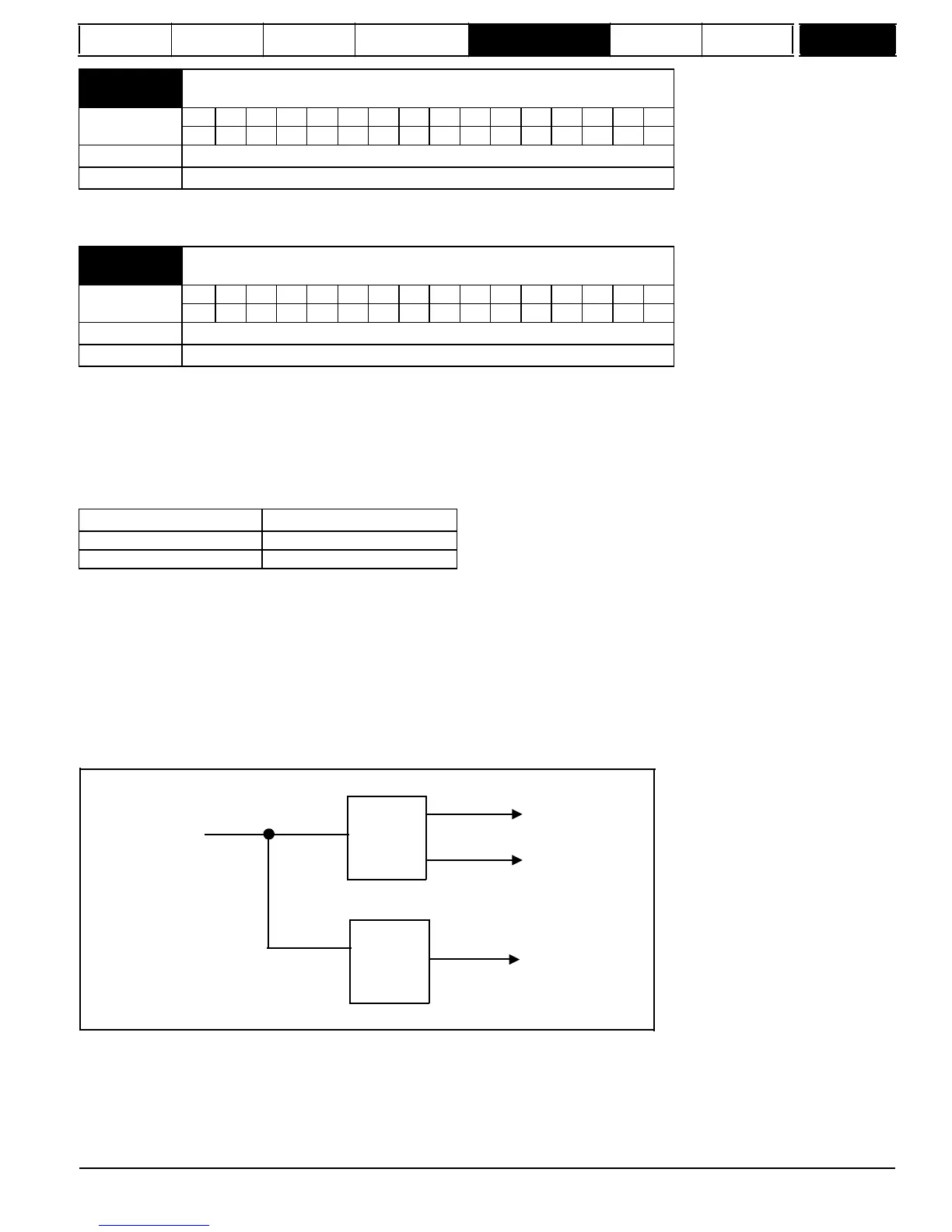
From the drive
encoder port
Filter
defined
by Pr
3.42
16ms
filter
Speed
controller
Drive encoder
reference
system
Pr
3.02
and
Pr
3.27
The diagram above shows the filter arrangement. It should be noted that the same filtering is provided at the speed controller input and for Pr
3.02
{
di05,
0.40
} when the feedback is obtained from an Solutions Module, but the variable length window filter is controlled by Pr
x.19
.
It is not advisable to set the speed feedback filter too high unless it is specifically required for high inertia applications with high controller gains
because the filter has a non-linear transfer function. It is preferable to use the current demand filters (see Pr
4.12
or Pr
4.23
) as these are linear first
order filters that provide filtering on noise generated from both the speed reference and the speed feedback. It should be noted that any filtering
included within the speed controller feedback loop, either on the speed feedback or the current demand, introduces a delay and limits the maximum
bandwidth of the controller for stable operation.
Mentor MP Advanced User Guide
43
Issue Number: 4
www.onxcontrol.com
3.01
 Loading...


