structure
Keypad and
format
Advanced
parameter
descriptions
Serial comms
Analog
input
scaling
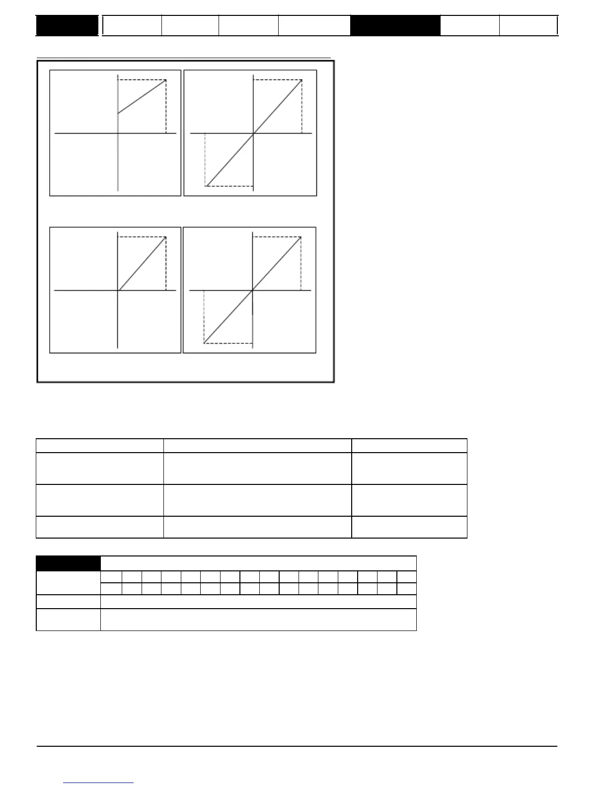
The following diagrams show the scaling applied when analog inputs are used to define the reference and are routed via Pr
1.36
or Pr
1.37
.
SPEED_MAX
Pr
1.07
-100%
100%
Pr
1.10
=0 (unipolar mode)
Pr
1.08
=0 (neg min ref disabled)
SPEED_MAX
-100%
100%
Pr
1.10
=0 (unipolar mode)
Pr
1.08
=1 (neg min ref enabled)
SPEED_MAX
-100%
100%
-SPEED_MAX
Pr
1.10
=1 (bipolar mode)
Pr
1.08
=0 (neg min ref disabled)
SPEED_MAX
-100%
100%
-SPEED_MAX
Pr
1.10
=1 (bipolar mode)
Pr
1.08
=1 (neg min ref enabled)
Reference
limits
With reference to the block diagram for Menu 1 (Figure 5-1 on page 22) the following table shows the limits applied to the reference by various blocks
in the reference system. It should be noted that the minimum limit in the main reference limits block changes when either the jog reference or velocity
feed forward references are active. When one of these is active: if Pr
1.08
= 0 the minimum = -Pr
1.06
{
SE02,
0.23
} [-Pr
21.01
for motor map2], if
Pr
1.01
{
di01,
0.36
} = selected reference x (100 + Pr
1.38
) / 100
and when this parameter is 1 the reference is given by
Pr
1.01
{
di01,
0.36
} = selected reference + Pr
1.04
26
Mentor MP Advanced User Guide
www.onxcontrol.com
Issue Number: 4
 Loading...


