Garmin G1000 Pilot’s Guide for the Diamond DA42NG
190-00962-04 Rev. A
50
FLIGHT INSTRUMENTS
SYSTEM
OVERVIEW
FLIGHT
INSTRUMENTS
EIS
AUDIO PANEL
& CNS
FLIGHT
MANAGEMENT
HAZARD
AVOIDANCE
AFCS
ADDITIONAL
FEATURES
APPENDICESINDEX
2.1 FLIGHT INSTRUMENTS
AIRSPEED INDICATOR
NOTE: Refer to the Aircraft Flight Manual (AFM) for airspeed criteria and Vspeed values.
The Airspeed Indicator displays airspeed on a moving tape rolling number gauge. The true airspeed is
displayed in knots below the Airspeed Indicator. The numeric labels and major tick marks on the moving
tape are shown at intervals of 10 knots. The minor tick marks on the moving tape are marked at intervals of
five knots. Speed indication starts at 20 knots, with 60 knots of airspeed viewable at any time. The indicated
airspeed is displayed inside the black pointer. The pointer remains black until reaching never-exceed speed
(V
NE
), at which point it appears red.
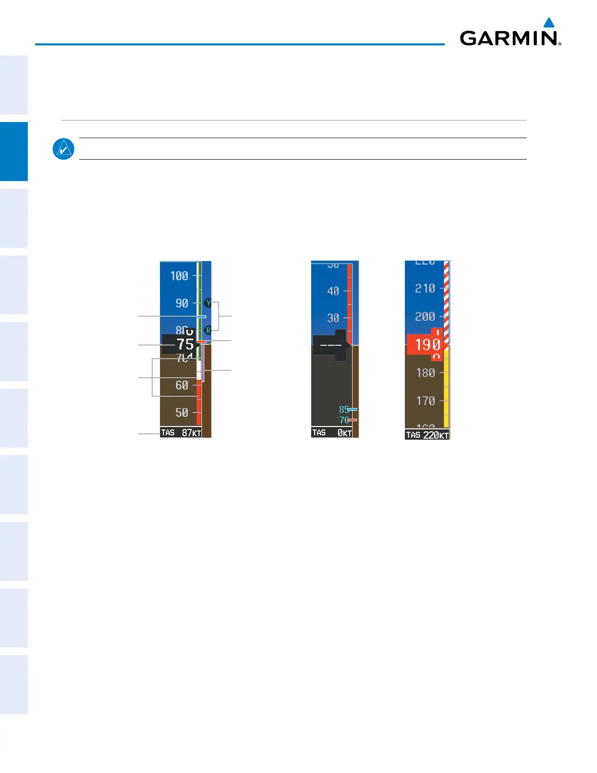
Figure 2-3 Example Airspeed Indicator Ranges
Red and White
Barber Pole at V
NE
Low Speed Range
Speed
Ranges
Indicated
Airspeed
True
Airspeed
Airspeed Indicator
Operating Ranges
Airspeed
Trend Vector
V
YSE
V
MCA
Vspeed
Bugs
Color coded stripes appear on the Airspeed Indicator to show the operating ranges. The low speed range
stripe is red. Normal operating range is green, caution range is amber, and the never exceed speed (V
NE
) begins
with a red and white barber pole. The flap operating range is indicated by a white stripe.
A red horizontal bar on the airspeed tape represents V
MCA
.
A cyan horizontal bar represents V
YSE
.
The Airspeed Trend Vector is a vertical magenta line that appears to the right of the color-coded speed range
strip when airspeed is either accelerating or decelerating. One end of the magenta line is anchored to the
tip of the airspeed pointer while the other end moves continuously up or down corresponding to the rate of
acceleration or deceleration. For any constant rate of acceleration or deceleration, the moving end of the line
shows approximately what the indicated airspeed value will be in six seconds. The trend vector is absent if the
speed remains constant or if any data needed to calculate airspeed is not available.

 Loading...


