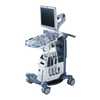
Definition of a Shell Contour (Geometry)
The basic idea of a
Shell Contour
is, to define a “thickness”’ of the “reference”’ surface
geometry.
The “’parallel” contours shown in the image define the “parallel” surface geometry (describing
the shell). The “parallel” contours are either defined symmetrically to the reference contour or
limited to one direction, inside or outside. The
Shell Geometry
consists of one outside and one
inside surface and therefore it is possible to distinguish between points enclosed by the shell
geometry and points outside of it. A
Shell Contour
represents all points enclosed by the inner
and outer surface geometry. If no
Shell Contour
is defined explicitly, the
Shell Geometry
consists of the reference surface (outside surface) and an inner point (the inside surface being
degenerated).
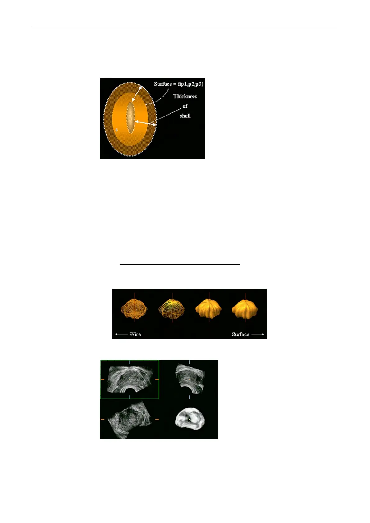
Display of a Shell Geometry (contour rendering)
The shell geometry can be visualized as “Skin” or “Wire Mesh”.
review:
Render Mode and Display of the Shell Geometry
(chapter
'VOCAL - Edit'
on page 9-
124
)
The image shows the different visualization techniques. VOCAL shows a surface Mesh.
Volume Rendered Image of a Shell Contour
The shell contour is used to define which voxels in the 3D ultrasound dataset are parts of the
shell geometry and which are outside. Voxels outside the shell contour are not displayed in the
Volume Rendered image.
Volume Mode
9-118
Voluson® S6/S8 Basic User Manual
5433669-100 Revision 4
 Loading...