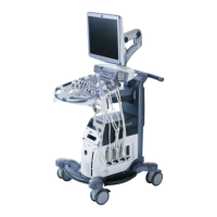
3. Select the next image plane by using the [Next] or [Back] key of the “Rotation Ref.:”
function.
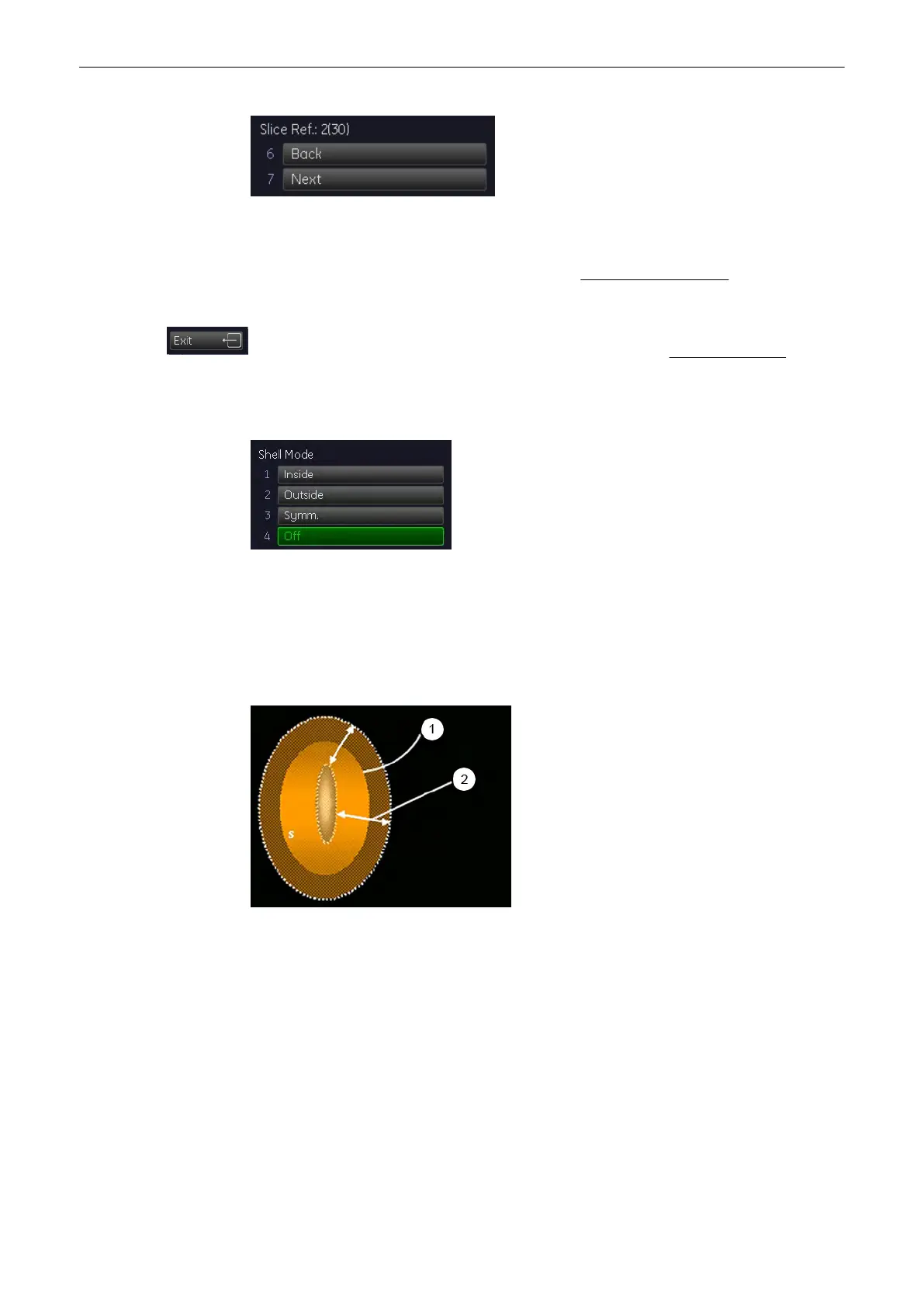
4. Select the desired Shell mode. For details, review: Defining a Shell contour
(chapter
'Defining a Shell contour (shell geometry)'
on page 9-126
)
5. After you have modified the contours in the selected image planes, select the[Accept ROI]
key. The shell contour is accepted and the result is displayed. The VOCAL - Static 3D menu
(chapter
'VOCAL - Static 3D'
on page 9-127
)
appears on the menu area.
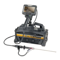
9.12.5.2 Defining a Shell contour (shell geometry)
Shell [OFF]
•
The outside surface (1) is equal to the generated contours (reference surface geometry).
•
The inside surface (1) is represented by an inner point (the inside surface is
degenerated).
Selection of other
Shell
states mean:
Shell [Inside]
•
The outside surface (1) is equal to the reference surface geometry (surface=f(p1,p2,p3).
•
The inside surface (1) is the surface geometry of the inner ’parallel’ contours with
distance
Shell Thickness
(2) in mm.
If one of the inside contours is not valid, the inside surface will not appear. (A contour is only
valid if the rotation axis is crossed exactly twice.)
Shell [Outside]
•
The outside surface (1) is the surface geometry of the outer ’parallel’ contours with
distance
Shell Thickness
in mm.
•
The inside surface (1) is equal to the reference surface geometry.
Volume Mode
9-126
Voluson® S6/S8 Basic User Manual
5433669-100 Revision 4