Home
GE
Diagnostic Equipment
Voluson S6
GE Voluson S6 User Manual
4
of 1
of 1 rating
684 pages
Give review
Manual
Specs
To Next Page
To Next Page
To Previous Page
To Previous Page
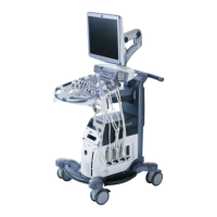
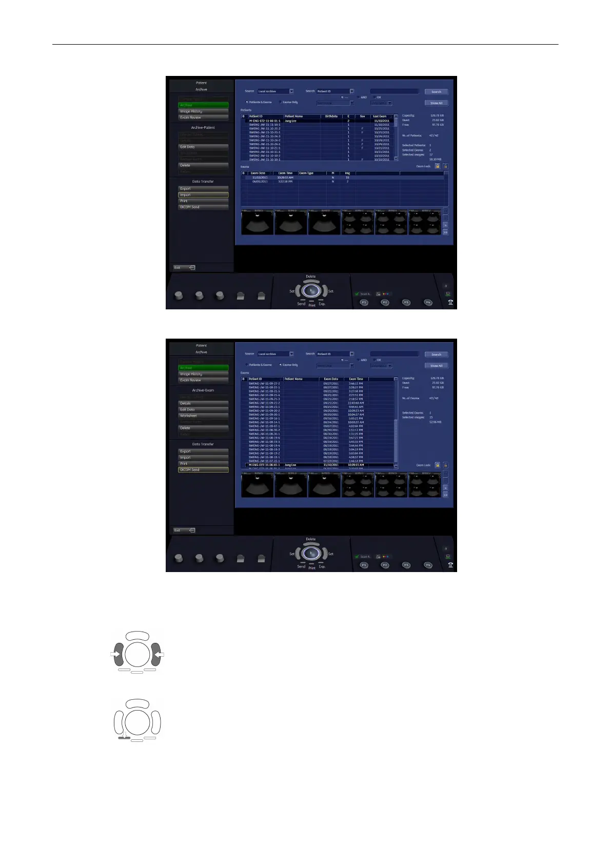
2.Archive Screen (Exam Only table)
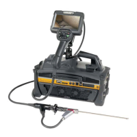
12.3.1 Trackball allocation
Press the left or right trackball key to set.
Press the lower, left trackball key to send and image to dicom. For more details, see 'Data
Transfer Menu'
on page 12-25
Archive
Voluson® S6/S8 Basic User Manual
5433669-100 Revision 4
12-11
514
516
Table of Contents
1 General
7
1.1 Contacting GE Healthcare Ultrasound
8
1.2 Manufacturer
13
1.3 About this User Manual
13
2 Safety
15
2.1 Warning labels used in the Basic User Manual
17
2.2 Symbols and Labels used on the system
17
2.3 Classification
20
2.4 Remarks for Safe Use
20
2.5 System Safety and Maintenance
21
2.5.1 Instructions for Use
21
2.5.2 Environmental Conditions for Operation
22
2.5.2.1 Electric Installation
23
2.5.2.2 Moving or lifting the System
23
2.5.3 ECG Module
24
2.5.4 Cleaning and Maintenance
25
2.5.4.1 Safety Test
27
2.5.4.2 Note for the Administration of “Full Backup” Data
27
2.6 Probe Safety and Maintenance
28
2.6.1 Handling Precautions
28
2.6.2 Watertightness
28
2.6.3 Electrical Shock Hazard
29
2.6.4 Mechanical Hazards
29
2.6.5 Cable Handling
29
2.6.6 Ergonomics
29
2.6.7 Probe Maintenance
30
2.6.7.1 Inspecting Probes
30
2.6.7.2 Probe Handling and Infection Control
30
2.6.7.3 Probe Cleaning and Disinfecting Process
30
2.6.7.4 Probe Immersion Levels
31
2.6.7.5 Planned Maintenance
32
2.6.7.6 Environmental requirements for Probes
32
2.6.7.7 Using Protective Sheaths
33
2.7 Biopsy Safety and Maintenance
33
2.7.1 Biopsy Special Concerns
33
2.7.1.1 Preparing the Patient
34
2.7.2 Biopsy Lines
34
2.8 Manufacturer Responsibility
35
2.9 Service Documents
35
2.9.1 Service Software – Remote Access
35
2.10 Bioeffects and Safety of Ultrasound Scans
36
2.10.1 Prudent Use – ALARA Principle
36
2.10.2 Bioeffects
36
2.10.3 Regulated Parameters
37
2.10.4 Interpretation of displayed parameters MI and TI
37
2.10.5 Reporting Tables
38
2.11 Disposal
38
3 Description of the System
41
3.1 Product Description
42
3.2 System Assembly
43
3.2.1 Optional Peripheral Devices
43
3.2.2 Optional Modules
43
3.3 Mechanical Adjustment
44
3.3.1 Mechanical Monitor Adjustment
44
3.3.1.1 Lock monitor parts
44
3.3.1.2 Preparing for transport
45
3.3.2 Mechanical Console Adjustment
45
3.3.2.1 Console-Transportlock
46
3.3.2.2 Horizontal Movement of the Control Console
46
3.3.2.3 Vertical Movement of the Control Console
46
3.3.3 Caster Brakes
46
3.4 Concept of Operation
47
3.4.1 Digipot controls, Trackball
47
3.4.2 Keyboard-Shortcut Functions
47
3.5 Layout of Menus
47
3.5.1 Layout of the 2D Mode Main Menu
47
3.5.2 Changing of Menus
48
3.5.3 Position of Display Annotation
49
3.5.3.1 Detailed Image information
50
3.5.4 Control Panel
51
3.6 Button description
51
3.6.1 Function of the Trackball at Diverse Dialog Pages
54
3.6.2 Keyboard keys
54
3.7 Remove USB Devices
55
3.8 Electronic User Manual (EUM)
56
3.8.1 Navigation Tools
57
3.8.2 Help Book - Navigation Tools
57
3.8.2.1 To View the Contents
58
3.8.2.2 To Use the Index
58
3.8.2.3 To Search for a Topic
59
3.8.2.4 To Save a Favorite Topic
60
3.8.3 To Exit the Electronic User Manual
60
4 Operating the System
61
4.1 General Remarks
62
4.2 Safety Warnings
62
4.3 Power On / Boot Up
62
4.4 Power Off / Shutdown
63
4.5 Transducer Connection
65
4.6 Prepareing the Transducer
65
4.6.1 Probe Usage
66
4.6.1.1 Coupling Gels
66
4.6.2 Probe Orientation
67
4.7 Probe/Program Selection
67
4.7.1 Starting the System
69
4.7.2 To Freeze an Image
69
4.8 Entering Patient Data
70
4.8.1 End Exam
70
4.8.2 Current Patient Menu
71
4.8.3 “Patient Information” screen
73
4.8.3.1 Patient Information – Abdomen (ABD)
75
4.8.3.2 Patient Information – Obstetrics (OB)
76
4.8.3.3 Patient Information – Gynecology (GYN)
79
4.8.3.4 Patient Information – Cardiology (CARD)
80
4.8.3.5 Patient Information – Urology (URO)
81
4.8.4 Standard Input
81
4.8.5 To Retrieve Patient Data via External Worklist Server
83
4.8.6 To Search in the Patient List
86
4.9 Image Annotation
87
4.9.1 Annotation
88
4.9.2 Auto Annotation
88
4.9.3 Indicator
90
4.9.4 Pictogram
90
4.10 Scan Assistant
92
4.10.1 Scan Assistant Details
93
4.10.1.1 Pause the Scan Assistant
93
5 Probes and Biopsies
95
5.1 Probes
96
5.1.1 Labeling
96
5.1.2 Applications
97
5.1.3 Features
98
5.1.4 Settings
99
5.1.5 Probe introduction
99
5.1.5.1 3D/4D Probes
100
5.1.5.2 Curved Array (Convex) Probes
101
5.1.5.3 Linear Array Probes
102
5.1.5.4 Phased Array Probes
103
5.1.5.5 Pencil probes
103
5.2 Biopsies
103
5.2.1 Biopsy guide mounting
103
5.2.2 Biopsy Setup
107
5.2.3 To program a Single Angle Biopsy Line
109
5.2.4 To program a Multi Angle Biopsy Line
110
5.2.5 Biopsy guide introduction
112
6 2D Mode
115
6.1 2D Main Menu
116
6.2 2D Operation
117
6.2.1 2D Gain
118
6.2.2 2D Mode Depth
118
6.2.3 2D Image Angle
119
6.2.4 TGC Slider Controls
119
6.2.5 2D Automatic Optimization
120
6.2.6 Transmit Power
120
6.2.7 Transmit Focus
120
6.2.8 Receiver Frequency Range
121
6.2.9 Harmonic Imaging (HI)
121
6.2.10 β-View (Beta View)
122
6.2.11 Focus and Frequency Composite (FFC)
122
6.2.12 Virtual Convex Mode
123
6.2.13 Wide Sector
123
6.2.14 Coded Excitation (CE)
123
6.2.15 CrossBeam Compound Resolution Imaging (XBeam CRI)
123
6.2.16 Speckle Reduction Imaging (SRI)
124
6.2.17 Image Orientation
124
6.2.18 Multi Format
124
6.2.18.1 Dual-Screen Format
125
6.2.18.2 Quad-Screen Format
126
6.2.19 Zoom
127
6.2.20 Normal Zoom
127
6.2.21 High Resolution Zoom
127
6.3 Cine Mode
129
6.3.1 Image Marker
131
6.3.2 Retrospective and Prospetive Cine Mode
131
6.3.3 Edit Clip
131
6.3.4 Cine-Split Function
132
6.3.5 2D Auto Cine
132
6.4 2D Sub Menu
134
6.4.1 Persistence Filter
135
6.4.2 Line Filter
135
6.4.3 CRI Filter
135
6.4.4 Dynamic Control
136
6.4.5 Optimized Tissue Imaging (OTI)
136
6.4.6 Enhance
136
6.4.7 Reject
136
6.4.8 Line Density
136
6.5 Gray Map
136
6.5.1 2D Gray Map
137
6.5.2 Tint Map
137
6.6 B-Flow
137
6.6.1 B-Flow Main Menu
138
6.6.2 B-Flow Operation
138
6.6.2.1 B-Flow Gain
138
6.6.2.2 Back- ground
139
6.6.2.3 Accu- mulation
139
6.6.2.4 Image Orientation
139
6.6.3 B-Flow Sub Menu
139
6.6.3.1 Persistence Filter
139
6.6.3.2 Line Density
139
6.6.3.3 Dynamic Control
139
6.6.3.4 Enhance
139
6.6.3.5 Sensitivity/PRI
139
6.7 XTD-View (Extended View)
140
6.7.1 XTD-View Main Menu
140
6.7.2 XTD-View Operation
142
6.7.3 Using XTD-View
142
6.7.4 After the XTD-View Image Acquisition
143
6.7.4.1 XTD Zoom
145
6.7.4.2 XTD Rotation
146
6.7.4.3 Frame Review
146
6.7.4.4 XTD Image Size
147
6.7.4.5 2D Zoom
147
6.7.4.6 Ruler
147
6.7.4.7 Measurements in the XTD-image
147
6.8 Contrast Imaging
148
6.8.1 Contrast Main Menu
148
6.8.2 Contrast Techniques
150
6.8.3 Contrast Operation
150
6.8.3.1 Enhance Max (maximum)
150
6.8.3.2 Speckle Reduction Imaging (SRI)
151
6.8.3.3 Contrast Clock
151
6.8.3.4 Time Delay
151
6.8.3.5 Zoom
151
6.8.3.6 Accu-mulation
151
6.8.3.7 Back-ground
152
6.8.4 Contrast Sub Menu
152
6.8.4.1 Persistence Filter
152
6.8.4.2 Line Density
152
6.8.4.3 Dynamic Control
152
6.8.4.4 Enhance
152
6.8.4.5 Sensitivity/PRI
152
7 M Mode
153
7.1 M Main Menu
154
7.1.1 Principle
155
7.2 M Operation
155
7.2.1 Cursor Position
156
7.2.2 Activation of M Mode
156
7.2.3 M Gain Control
156
7.2.4 Sweep Speed
157
7.2.5 Invert
157
7.2.6 Frequency
157
7.2.7 TGC Slider Controls
157
7.2.8 Transmit Power
157
7.2.9 M Mode Depth
158
7.2.10 M Cineloop
158
7.3 M Sub Menu
158
7.3.1 Reject
159
7.3.2 Enhance
160
7.3.3 Dynamic Control
160
7.3.4 Display Size
160
7.3.5 Display Format
160
7.4 MCF Mode (M Color Flow Mode)
160
7.4.1 MCF Main Menu
161
7.4.2 MCF Operation
162
7.4.2.1 Color Box Size and Cursor Position
162
7.4.2.2 Activation of MCF Mode
162
7.4.2.3 MCF Gain Control
163
7.4.2.4 Invert
163
7.4.2.5 Wall Motion Filter (WMF)
163
7.4.2.6 Velocity Range (PRF)
163
7.4.2.7 MCF Cineloop
163
7.4.3 MCF Sub Menu
163
7.5 MTD Mode (M Tissue Doppler Mode)
164
7.5.1 MTD Main Menu
165
7.5.2 MTD Operation
166
7.5.2.1 Color Box Size and Cursor Position
166
7.5.2.2 Activation of MTD Mode
166
7.5.2.3 MTD Gain Control
167
7.5.2.4 Invert MTD
167
7.5.2.5 Velocity Range (PRF)
167
7.5.2.6 MTD Cineloop
167
7.5.3 MTD Sub Menu
167
7.6 MHDF Mode (MHD-Flow Mode)
168
7.6.1 MHDF Main Menu
169
7.6.2 MHDF Operation
170
7.6.2.1 Color Box Size and Cursor Position
170
7.6.2.2 Activation of MHDF Mode
170
7.6.2.3 MHDF Gain Control
171
7.6.2.4 Invert
171
7.6.2.5 Wall Motion Filter (WMF)
171
7.6.2.6 Velocity Range (PRF)
171
7.6.2.7 MHDF Cineloop
171
7.6.3 MHDF Sub Menu
171
7.7 STIC with M-Mode
172
7.8 Anatomical M-Mode (AMM)
173
7.8.1 AMM Main Menu
173
7.8.1.1 View Modes
174
7.8.1.2 Rotate
175
7.8.2 AMM Sub menu
175
8 Doppler Modes
177
8.1 Pulsed Wave Doppler Mode (PW Mode)
178
8.1.1 PW Main Menu
179
8.1.2 PW Operation
180
8.1.2.1 Gate Position and Gate Width
180
8.1.2.2 Activation of PW Mode
181
8.1.2.3 PW Gain Control
181
8.1.2.4 PW Automatic Optimization
181
8.1.2.5 Freeze
182
8.1.2.6 PW Cineloop
182
8.1.3 PW Sub Menu
182
8.1.4 PW + 2D + Color Information (Triplex Mode)
183
8.2 Continuous Wave Doppler Mode (CW Mode)
184
8.2.1 CW Main Menu
184
8.2.2 CW Operation
185
8.2.2.1 Cursor Position and Focus
186
8.2.2.2 Activation of CW Mode
186
8.2.2.3 CW Gain Control
186
8.2.3 CW Sub Menu
186
8.2.3.1 View Modes
187
8.2.4 CW + 2D + Color Information (Triplex Mode)
187
8.3 Color Flow Mode (CFM)
188
8.3.1 CF Main Menu
189
8.3.2 CF Operation
190
8.3.2.1 CF Box Position and CF Box Size
190
8.3.2.2 CF Gain Control
191
8.3.2.3 2D + 2D/C
191
8.3.3 CF Sub Menu
191
8.3.3.1 CF Map and Display Mode
193
8.3.4 CF + 2D + Spectral Doppler (Triplex Mode)
193
8.4 Power Doppler Mode (PD Mode)
193
8.4.1 PD Main Menu
194
8.4.2 PD Operation
195
8.4.2.1 PD Box Position and PD Box Size
196
8.4.2.2 PD Gain Control
196
8.4.2.3 2D + 2D/PD
196
8.4.3 PD Sub Menu
197
8.4.3.1 PD Map
198
8.4.4 PD + 2D + Spectral Doppler (Triplex Mode)
198
8.5 HD-Flow Mode (Bi-directional Angio Mode)
199
8.5.1 HD-Flow Main Menu
199
8.5.2 HD-Flow Operation
200
8.5.2.1 HD-Flow Box Position and HD-Flow Box Size
201
8.5.2.2 HD-Flow Gain Control
201
8.5.2.3 2D + 2D/HDF
201
8.5.3 HD-Flow Sub Menu
202
8.5.3.1 HDF Map
202
8.5.4 HD-Flow + 2D + Spectral Doppler (Triplex Mode)
203
8.6 Tissue Doppler Mode (TD Mode )
203
8.6.1 TD Main Menu
204
8.6.2 TD Operation
205
8.6.2.1 TD Box Position and TD Box Size
205
8.6.2.2 TD Gain Control
205
8.6.2.3 2D + 2D/TD
206
8.6.3 TD Sub Menu
206
8.6.3.1 TD Map
207
8.7 Doppler Mode Functions and Filters
207
8.7.1 Angle Correction
207
8.7.2 Artifact Suppression
208
8.7.3 Audio Signal
208
8.7.4 Balance
208
8.7.5 Baseline
209
8.7.6 Dynamic
209
8.7.7 Ensemble
209
8.7.7.1 Ensemble for TD
210
8.7.8 Flow Resolution
210
8.7.9 Size
210
8.7.10 Format
211
8.7.11 Frequency
212
8.7.11.1 Frequency for Elastography
212
8.7.12 Gently Colors
213
8.7.13 Invert
213
8.7.14 Line Density
213
8.7.15 Line Filter
214
8.7.16 Quality
214
8.7.17 Real Time Trace
214
8.7.18 Scale
215
8.7.19 Smoothing
215
8.7.20 Sweep Speed
216
8.7.21 Threshold
216
8.7.22 Velocity Range (PRF)
216
8.7.22.1 HPPRF
217
8.7.23 Wall Motion Filter (WMF)
217
8.7.23.1 WMF for PW
218
9 Volume Mode
219
9.1 Volume Acquisition with Volume Probes
220
9.1.1 Principle of Volume Acquisition
224
9.1.2 Principal Scanning Modes
225
9.1.3 What is Interactive 3D Image Rendering?
225
9.1.3.1 What is Interactive?
226
9.1.4 Image Orientation (All Acquisition Modes)
226
9.1.5 Orientationhelp for 3D/4D data sets (Probe Orientation)
228
9.1.6 The Render Box
232
9.1.7 General Advices to Obtain Good Rendered 3D Images
233
9.1.7.1 Examples of Rendered Images
234
9.2 Volume Acquisition: Static 3D Sectional Planes
234
9.2.1 3D Acquisition During Active High Resolution Zoom
237
9.2.2 During 3D Acquisition
238
9.2.3 After the Static 3D Sectional Planes Acquisition
239
9.2.3.1 Orientation Help Graphic
240
9.2.3.2 Automatic Optimization in Volume PreMode
241
9.2.3.3 Reference Image
241
9.2.3.4 Image Position
242
9.2.3.5 Image Magnifier
242
9.2.3.6 Initial Condition
242
9.2.4 Principle of Sectional Image Analysis
242
9.2.4.1 Rotations
244
9.2.4.2 Translation
246
9.2.4.3 Initial Condition of different Probes
247
9.2.4.4 Initial Condition of different Probes
251
9.2.4.5 A,B,C - Sectional Plane Mode
252
9.2.4.6 Reference Image Mode
252
9.2.4.7 Niche Display Mode
253
9.2.4.8 VCI Static
256
9.2.5 Tomographic Ultrasound Imaging – TUI (Parallel Slices)
257
9.3 Sub Menus
261
9.3.1 Render View Direction
263
9.3.2 3D/4D Info
263
9.3.3 3D Color Off
264
9.3.4 Speckle Reduction Imaging (SRI)
264
9.3.5 3D Gray Chroma Map
265
9.3.6 Contrast
265
9.3.7 Background
265
9.3.8 Balance
265
9.3.9 Power Threshold
266
9.4 Volume Acquisition: Static 3D Render
266
9.4.1 After the Static 3D Render Acquisition
269
9.4.1.1 3D ROI (Edit ROI) Mode
270
9.4.1.2 Adjust Position, Size and Curvature of the Render Box
271
9.4.1.3 3D Pictogram (Accept ROI) Mode
272
9.4.2 Cine Calculation
275
9.4.2.1 3D Rotational Cine
277
9.4.2.2 3D Translational Cine
279
9.4.2.3 Slice Cine
281
9.4.2.4 Calculating a Cine
283
9.4.2.5 During Display of a Cine
284
9.4.2.6 Changing the Kind of Cine
286
9.4.3 MagiCut
287
9.4.3.1 MagiCut Operation
287
9.4.4 Render Mode - Image Type and Render Algorithm
290
9.4.4.1 Gray Render Mode
291
9.4.4.1.1 Threshold Control in Gray Render Mode
292
9.4.4.1.2 Transparency in Gray Render Mode
293
9.4.4.2 Color Render Mode
293
9.4.4.2.1 Threshold Control in Color Render Mode
294
9.4.4.2.2 Transparency in Color Render Mode
294
9.4.4.3 Glass Body Render Mode
294
9.4.4.4 Inversion Render Mode
295
9.4.4.5 Measurements in rendered image
295
9.5 Real Time 4D Acquisition
296
9.5.1 Possible Display Adjustment before a Real Time 4D Acquisition
299
9.5.2 Real Time 4D Acquisition During Active High Resolution Zoom
300
9.5.2.1 Display of Sectional Planes
301
9.5.2.2 Display of REF-Image
302
9.5.2.3 Display of ROI 4D
304
9.5.2.4 Display of 4D
305
9.5.2.5 Display of A-ROI 4D
306
9.5.2.5.1 4D ROI (Edit ROI) Mode
308
9.5.2.5.2 Accept ROI Mode
308
9.5.3 MagiCut 4D
308
9.5.3.1 MagiCut 4D Operation
309
9.5.4 4D Controls
310
9.5.4.1 Available Controls before the acquisition
310
9.5.4.2 Available Controls during and after the acquisition
310
9.6 Sono Render Start
312
9.7 Volume Cine
313
9.7.1 Volume Cine
316
9.8 Volume Contrast Imaging: (VCI A-Plane)
317
9.8.1 VCI-A Controls
319
9.8.2 After the VCI-A Acquisition
320
9.9 VCI-Omniview
320
9.9.1 VCI-Omni View Controls
322
9.9.2 VCI-Omni View Curve Line
323
9.9.3 After the VCI-Omni View Acquisition
324
9.9.4 Omni View Ref. Line
324
9.10 STIC (Spatio-Temporal Image Correlation)
325
9.10.1 STIC Oncology
329
9.10.2 After STIC Calculation
330
9.10.2.1 Measurements in the STIC-image
331
9.11 Real Time 4D Biopsy
331
9.11.1 Real Time 4D Biopsy Controls
333
9.11.2 After the Real Time 4D Biopsy
334
9.12 VOCALII
334
9.12.1 Definitions
335
9.12.2 VOCAL - Define a new Contour
337
9.12.3 VOCAL Settings
339
9.12.4 Selection of a VOCAL Generation Mode
340
9.12.4.1 Manual - Trace
340
9.12.4.2 Automatic - Sphere
341
9.12.4.3 Save VOCAL
342
9.12.5 VOCAL - Edit
342
9.12.5.1 Modifying a Contour
343
9.12.5.2 Defining a Shell contour (shell geometry)
344
9.12.5.3 Display of the (Shell) Volume
345
9.12.5.4 VOCAL - Static 3D
345
9.12.5.5 Render Mode and Display of the Shell Geometry
347
9.12.5.6 Threshold Volume
348
9.12.5.7 Vocal Measurement Display
348
9.12.5.8 Volume Histogram
349
9.13 SonoAVC Follicle
349
9.13.1 General Information
349
9.13.2 Operation
350
9.13.2.1 Table of low echogenic objects
351
9.14 VCAD Heart - Volume Computer Aided Display
354
9.14.1 General Description
355
9.14.2 Operation
355
9.14.3 Before VCAD Operation
359
9.14.4 During VCAD Operation
360
9.15 SonoVCAD labor
361
9.15.1 Operation
361
9.15.2 Mark pubis position - Auto Adjust
362
9.15.3 Mark pubis position - manual
363
9.15.4 Set fetal contour
364
9.15.5 Set head direction
364
9.15.6 Set midline
365
9.15.7 Head progression distance
366
9.15.8 Head progression angle
366
10 Elastography Mode
369
10.1 GUI elements
370
10.1.1 Quality bar
371
10.2 Elastography Main Menu
371
10.2.1 SRI
372
10.2.2 2D+2D/Elasto
372
10.2.3 Transparency
372
10.2.4 Frequency
373
10.2.5 PRF
373
10.3 Elastography Sub Menu
373
10.3.1 Elasto Map
373
10.3.2 Persist.
373
10.3.3 Line Dens.
373
10.3.4 Window Length
374
10.3.5 Window Step
374
10.3.6 Filter Axial
374
10.3.7 Filter Lateral
374
10.3.8 Frame Reject
374
10.3.9 Pixel Reject
374
10.4 Elastography Sub Menu 2
374
10.4.1 AGC Filter Axial
375
10.4.2 AGC Filter Lateral
375
10.4.3 AGC Threshold High
375
10.4.4 AGC Threshold Low
375
10.4.5 Frame Averaging
375
11 Measurements and Patient Worksheets (Reports)
377
11.1 Generic Measurements
378
11.1.1 Basic Operations
379
11.1.2 2D Mode Measurements
381
11.1.2.1 Generic Distance Measurements
382
11.1.2.1.1 Distance 2 Points
383
11.1.2.1.2 Distance 2 Lines
383
11.1.2.1.3 Length Trace
383
11.1.2.1.4 Length Point
383
11.1.2.1.5 Stenosis %Distance
383
11.1.2.2 Generic Area Measurements
384
11.1.2.2.1 Area Trace
384
11.1.2.2.2 Area Point
384
11.1.2.2.3 Area 2 Distances
385
11.1.2.2.4 Ellipse
385
11.1.2.2.5 Stenosis %Area
385
11.1.2.3 Generic Volume Measurement
386
11.1.2.3.1 3 Distances
386
11.1.2.3.2 Ellipse
387
11.1.2.3.3 1 Distance + Ellipse
387
11.1.2.3.4 1 Distance
387
11.1.2.3.5 Multiplane
387
11.1.2.4 Generic Angle Measurement
389
11.1.2.4.1 Angle 3 Point
389
11.1.2.4.2 Angle 2 Line
390
11.1.3 M-Mode Measurements
390
11.1.3.1 Generic Measurements
391
11.1.3.1.1 Distance 2 Points
391
11.1.3.1.2 Slope
391
11.1.3.1.3 Time
391
11.1.3.1.4 Stenosis %Distance
392
11.1.3.1.5 HR (Heart Rate)
392
11.1.4 D-Mode Measurements
392
11.1.4.1 Generic Measurements
393
11.1.4.1.1 Auto Trace
393
11.1.4.1.2 Manual Trace
394
11.1.4.1.3 Velocity
394
11.1.4.1.4 Acceleration
394
11.1.4.1.5 RI (Resistivity Index)
394
11.1.4.1.6 PI (Pulsatility Index)
395
11.1.4.1.7 PS/ED (Peak Systole/End Diastole Ratio)
395
11.1.4.1.8 Time
395
11.1.4.1.9 HR (Heart Rate)
395
11.1.4.2 PG (Pressure Gradient) Measurements
396
11.1.4.2.1 PG max (Pressure Gradient maximum)
396
11.1.4.2.2 PG mean (Pressure Gradient mean)
396
11.1.5 To Change the Measurement Application
396
11.1.6 To Review the Generic Work Sheet
397
11.1.7 Measurement Accuracy of the System
399
11.2 Calculations and Worksheets
399
11.2.1 Calculation Packages
399
11.2.2 Abdomen Calculations
400
11.2.2.1 Items of Abdomen Calculations
400
11.2.2.2 Before starting Abdomen Calculations
401
11.2.2.3 Abdomen Calculations in 2D Mode
401
11.2.2.4 Distance Measurements
401
11.2.2.5 Vessel Area/Vessel Diameter
402
11.2.2.6 Stenosis Area/Stenosis Diameter
404
11.2.2.7 Abdomen Calculations in M Mode
404
11.2.2.8 Vessel Diameter
405
11.2.2.9 Stenosis Diameter
405
11.2.2.10 Time
405
11.2.2.11 HR (Heart Rate)
406
11.2.2.12 Abdomen Calculations in Spectral-Doppler Mode
406
11.2.2.13 Auto Trace
407
11.2.2.14 Manual Trace
408
11.2.2.15 Measurement of Each Item
408
11.2.2.16 Measurement of PSV/EDV RI+SD
408
11.2.2.17 Time
409
11.2.2.18 HR (Heart Rate)
409
11.2.2.19 Abdomen Worksheet
409
11.2.3 Small Parts Calculations
410
11.2.3.1 Items of Small Parts Calculations - Subcategory: Default
410
11.2.3.2 Items of Small Parts Calculations - Subcategory: Breast
410
11.2.3.3 Before starting Small Parts Calculations
411
11.2.3.4 Small Parts Calculations in 2D Mode
411
11.2.3.5 Small Parts Calculations in M Mode
411
11.2.3.6 Small Parts Calculations in Spectral-Doppler Mode
411
11.2.3.7 Small Parts - Worksheet
412
11.2.4 Obstetric Calculations - Subcategory: Biometry
413
11.2.4.1 Items of Obstetric Calculations - Subcategory: Biometry
413
11.2.4.2 Before starting Obstetric Calculations
414
11.2.4.3 Obstetric Calculations in 2D Mode
415
11.2.4.4 Distance Measurements
416
11.2.4.5 To calculate GS (Gestational Sac)
416
11.2.4.6 Circumference Measurements
418
11.2.4.7 AFI Calculation
419
11.2.4.8 Early Gest. - NT
419
11.2.4.9 Display of 2D Measurement Results
421
11.2.4.10 Obstetric Calculations in M Mode
423
11.2.4.11 Obstetric Calculations in Spectral-Doppler Mode
423
11.2.4.12 FHR (Fetal Heart Rate)
423
11.2.4.13 Obstetrics - Subcategory Z-Scores
424
11.2.4.14 Items of Obstetric Calculations - Subcategory: Z-scores
424
11.2.4.15 Before starting Obstetric Calculations
424
11.2.4.16 Obstetric Calculations in 2D Mode
425
11.2.4.17 Distance Measurements
426
11.2.4.18 To obtain Z-Scores
427
11.2.4.19 Echocardiac views
427
11.2.4.20 Fractional Limb
428
11.2.4.21 Obstetric - Subcategory: Fetal Echo
429
11.2.4.22 Items of Obstetric Calculations - Subcategory: Fetal Echo
429
11.2.4.23 Obstetric - Worksheet
429
11.2.4.24 Summary Report - Calc
431
11.2.4.25 Summary Report - Fetal Anatomy
431
11.2.4.26 Summary Report - Graph
432
11.2.4.27 Summary Report - Fetus Compare
435
11.2.4.28 Summary Report - Generic
435
11.2.4.29 Summary Report - Exam Comment
436
11.2.5 Cardiac Calculations
436
11.2.5.1 Items of Cardiology Calculations
436
11.2.5.2 Before Starting Cardiology Calculations
436
11.2.5.3 Cardiology Calculations in 2D Mode
437
11.2.5.4 LV Simpson
438
11.2.5.5 Vol A/L (Volume Area/Length)
438
11.2.5.6 LV (Left Ventricle)
440
11.2.5.7 LV Mass
440
11.2.5.8 LVOT- or RVOT Diameter
441
11.2.5.9 MV (Mitral Valve)
443
11.2.5.10 TV (Tricuspid Valve)
443
11.2.5.11 AV/LA (Aortic Valve/Left Atrium)
444
11.2.5.12 PV (Pulmonary Valve)
444
11.2.5.13 Cardiology Calculations in CFM Mode
444
11.2.5.14 PISA
444
11.2.5.15 Cardiology Calculations in M Mode
445
11.2.5.16 LV (Left Ventricle)
445
11.2.5.17 To measure all Items at a Time
446
11.2.5.18 To measure the Items One by One
447
11.2.5.19 AV/LA (Aortic Valve/Left Atrium)
447
11.2.5.20 MV (Mitral Valve)
448
11.2.5.21 To measure all Items at a Time
448
11.2.5.22 To measure the Items One by One
449
11.2.5.23 HR (Heart Rate)
449
11.2.5.24 Cardiology Calculations in Spectral-Doppler Mode
450
11.2.5.25 MV (Mitral Valve)
451
11.2.5.26 Manual Trace
451
11.2.5.27 To measure the Items One by One
452
11.2.5.28 AV (Aortic Valve)
452
11.2.5.29 TV (Tricuspid Valve)
453
11.2.5.30 PV (Pulmonary Valve)
454
11.2.5.31 LVOT- or RVOT Doppler
455
11.2.5.32 Pulmonary Veins
455
11.2.5.33 PAP (Pulmonary Artery Pressure Measurement)
456
11.2.5.34 HR (Heart Rate)
457
11.2.5.35 Cardiology - Worksheet
457
11.2.6 Urology Calculations
458
11.2.6.1 Items of Urology Calculations
458
11.2.6.2 Before starting Urology Calculations
459
11.2.6.3 Urology Calculations in 2D Mode
459
11.2.6.4 Urology Calculations in M Mode
459
11.2.6.5 Urology Calculations in Spectral-Doppler Mode
459
11.2.6.6 Urology - Worksheet
460
11.2.7 Vascular Calculations
460
11.2.7.1 Items of Vascular Calculations
461
11.2.7.2 Before starting Vascular Calculations
461
11.2.7.3 Vascular Calculations in 2D Mode
461
11.2.7.4 Vascular Calculations in M Mode
462
11.2.7.5 Vascular Calculations in Spectral-Doppler Mode
462
11.2.7.6 Vascular - Worksheet
462
11.2.8 Gynecology Calculations
463
11.2.8.1 Items of Gynecology Calculations
464
11.2.8.2 Before starting Gynecology Calculations
464
11.2.8.3 Gynecology Calculations in 2D Mode
465
11.2.8.4 Gynecology Calculations in M Mode
465
11.2.8.5 Gynecology Calculations in Spectral-Doppler Mode
465
11.2.8.6 Gynecology - Worksheet
466
11.2.9 Pediatric Calculations
467
11.2.9.1 Items of Pediatric Calculations
467
11.2.9.2 Before starting Pediatric Calculations
467
11.2.9.3 Pediatric Calculations in 2D Mode
467
11.2.9.4 Hip Joint
468
11.2.9.5 Pediatric Calculations in M Mode
469
11.2.9.6 Pediatric Calculations in Spectral-Doppler Mode
469
11.2.9.7 Pediatric - Worksheet
469
11.2.10 Neurology Calculations
470
11.2.10.1 Items of Neurology Calculations
470
11.2.10.2 Before starting Neurology Calculations
471
11.2.10.3 Neurology Calculations in 2D Mode
471
11.2.10.4 Neurology Calculations in M Mode
471
11.2.10.5 Neurology Calculations in Spectral-Doppler Mode
471
11.2.10.6 Neurology Worksheet
472
11.2.11 MSK Calculations
473
11.2.11.1 Items of MSK Calculations
473
11.2.11.2 Before starting MSK Calculations
473
11.2.11.3 MSK - Worksheet
473
11.3 Basic Calculation Functionality
474
11.4 Basic Patient Worksheet Functions
477
11.4.1 To view a Worksheet
477
11.4.2 To edit a Worksheet
479
11.4.3 To change the Application
479
11.4.4 Exam Comment
479
11.4.5 To transfer a Worksheet
481
11.4.6 To view previous Worksheets
481
11.4.7 To print a Report
482
11.5 Measure Setup
483
11.5.1 To Invoke the Setup Procedure
484
11.5.2 To Exit from the Measure Setup
485
11.5.3 The Measure Setup Pages
485
11.5.3.1 Measure & Calc
485
11.5.3.1.1 To Add a Sub Category, Study or Measure Item
487
To Create a New Measurement or Calculation Item
488
11.5.3.1.2 To Delete a Sub Category, Study or Measure Item
493
11.5.3.1.3 To Rearrange Sub Categories, Studies or Measure Items
493
11.5.3.1.4 To Edit a Sub Category, Study or Measure Item
494
To Display the exact Table or Equation
495
11.5.3.1.5 To Copy Settings
496
11.5.3.1.6 To Change the Report Order
496
11.5.3.1.7 First Trimester OB in application GYN
497
11.5.3.1.8 EFW (Estimated Fetal Weight)
498
Estimation
499
Age by EFW
499
EFW GP/SD
500
11.5.3.2 Application Parameters
500
11.5.3.3 Global Parameters
503
12 Archive
505
12.1 Current Patient Dialog
507
12.1.1 Patient Data Area
508
12.1.2 Application Area
508
12.1.2.1 Scan Assistant
508
12.1.3 Additional Study Information Area
508
12.1.4 Exam Display
510
12.2 Clipboard
510
12.2.1 Appearances of the Clipboard
511
12.2.1.1 Changing pages
511
12.2.1.2 Saving onto the Clipboard
511
12.2.2 Manipulating Files on the Clipboard
512
12.2.2.1 Reload from the Clipboard
512
12.2.2.2 Export from the Clipboard
512
12.2.2.3 Deletion from the Clipboard
512
12.2.3 Saving Files to Archive
513
12.2.4 Image Indices
513
12.2.4.1 Indices
513
12.2.4.2 Export Symbol
513
12.2.4.3 Deletion Mark
514
12.2.4.4 Open Image
514
12.2.4.5 Tool Tip
514
12.3 Patient Archive
514
12.3.1 Trackball allocation
515
12.3.2 Lock or unlock selected exams
516
12.3.3 Searching for a Particular Exam
517
12.3.3.1 Search Area
517
12.3.3.1.1 How to search
518
12.3.3.2 Patient Table
519
12.3.3.3 Exam Table
519
12.3.3.4 Image Area
520
12.3.3.5 DICOM Server (Query/Retrieve)
520
12.3.3.6 DICOM Details
523
12.3.4 Patient Menu
523
12.3.4.1 Use as Current
524
12.3.4.2 Edit Data Menu
524
12.3.4.3 Data Transfer Menu
525
12.3.5 Exam Menu
525
12.3.5.1 Reopen Exam
526
12.3.5.2 Exam Details
527
12.3.5.3 Worksheet
527
12.3.5.4 Data Transfer Menu
528
12.3.6 Image Area
528
12.3.6.1 Image Properties
528
12.3.6.2 Data Transfer Menu
529
12.3.7 Data Transfer Menu
529
12.3.7.1 DICOM Send
529
12.3.7.2 Print
530
12.3.7.3 Export
531
12.3.7.4 Fast Export
533
12.3.7.5 Import
533
12.3.7.6 Delete
534
12.4 Image History
534
12.5 Exam Review
535
12.5.1 Opening Exam Review
537
12.5.1.1 Exam Review Screen
538
12.5.2 End Exam
538
12.5.2.1 Setup Switch “End Exam Dialog” OFF
538
12.5.2.2 Setup Switch “End Exam Dialog” ON
538
12.5.3 Reload
539
12.5.4 Repro
540
12.5.5 Commenting
541
12.5.5.1 Exam Comment
541
12.5.5.2 Image Comment
541
12.5.6 Formats
542
12.5.7 Buttons
542
12.5.8 Images with JPEG Compression (less than 100%)
543
12.6 Selecting Exams
543
12.6.1 To Use the Exams Only List
544
12.6.2 To Select the Exams
544
12.6.3 To Sort the Exams
545
12.6.4 To Search for Exams
545
12.7 Settings
545
13 Utilities and System Setup
547
13.1 Utilities
548
13.1.1 Changing Brightness of the UI and Master Volume
549
13.1.2 Monitor
549
13.1.3 Histogram
551
13.1.3.1 2D Histogram
551
13.1.3.2 3D Histogram
553
13.1.3.3 Volume Histogram
553
13.1.4 Thermal Indices
553
13.1.5 Display of Biopsy Guideline
554
13.1.6 Lock Screen
554
13.1.6.1 Introduction
554
13.1.6.2 Enabling Lock Screen
555
13.1.6.3 Emergency Mode
557
13.1.6.4 Changing Password
558
13.2 System Setup
558
13.2.1 To invoke the Setup Procedure
560
13.2.2 To Exit from the Setup Procedure
560
13.2.3 General
561
13.2.3.1 General filing card
561
13.2.3.1.1 To Enter Date, Time and Time Zone
561
13.2.3.1.2 To Change the Time Format
562
13.2.3.1.3 Date Format
563
13.2.3.1.4 Display
563
13.2.3.1.5 Clinic Name
563
13.2.3.1.6 Screen- saver Text
563
13.2.3.1.7 Language
563
13.2.3.1.8 EUM Language
563
13.2.3.1.9 Presentation Mode
564
13.2.3.2 User Settings
565
13.2.3.2.1 Clipboard
566
13.2.3.2.2 To Save a User Program
566
13.2.3.2.3 To Save a 3D/4D Program
567
13.2.3.2.4 To Enter/Overwrite Text Auto
568
13.2.3.2.5 To Adjust the Trackball Speed
570
13.2.3.3 Patient Info Display
571
13.2.3.3.1 Exam Table Columns
572
13.2.3.3.2 Drop Down Management
572
13.2.3.3.3 2nd Patient ID
572
13.2.3.3.4 Various Checkboxes
572
13.2.3.3.5 Automatically List Patients
573
13.2.3.3.6 Title Bar Settings
573
13.2.3.3.7 Archive: customize Exam columss
573
13.2.4 Administration
573
13.2.4.1 Service
573
13.2.4.2 System Info
574
13.2.4.3 Options
575
13.2.5 Connectivity
576
13.2.5.1 Peripherals
576
13.2.5.2 Device Setup
577
13.2.5.2.1 DICOM Configuration
577
To Specify a DICOM Address
579
13.2.5.2.2 DICOM Queue Status
583
13.2.5.2.3 Network Configuration
585
13.2.5.2.4 Archive Configuration
586
13.2.5.2.5 WLAN Configuration
587
13.2.5.3 Network profiles
588
13.2.5.4 Button Configuration
590
13.2.5.5 Drives
590
13.2.6 Backup
593
13.2.6.1 System Configuration
593
13.2.6.1.1 Save Image Settings
594
13.2.6.1.2 Load Image Settings Only
594
13.2.6.1.3 Save Full System Configuration
596
13.2.6.1.4 Load Full System Configuration
599
13.2.6.1.5 Delete Full System Configuration
601
13.2.6.1.6 Working with external USB-Devices
602
13.2.6.2 Image Archive
602
13.2.6.2.1 How to Load an Archive
602
13.2.6.2.2 How to Save an Archive
605
13.2.7 Measure Setup
607
13.2.8 Scan Assistant Settings
608
14 Programmable Keys
611
14.1 Where to program the keys
612
14.2 P-keys
614
14.2.1 Overview tab
616
14.2.2 Detailed Setup
617
14.3 Start Exam Button
619
14.4 End Exam Button
620
15 Connections
623
15.1 How to Connect Auxiliary Devices Safely
624
15.1.1 Important Notes: Connecting Auxiliary Equipmen
625
15.2 To Connect Internal and External Accessories
625
15.3 Connection between Internal I/O and External I/O
626
15.3.1 Internal and external I/O
626
15.3.2 Power Supply (rear side)
627
15.3.3 Power Supply (for on-board peripherals)
627
15.3.4 Connector Panels
627
15.3.4.1 Rear Panel
627
15.3.4.2 Upper OPIO Panel
629
15.4 Connection of Peripherals
629
15.4.1 User installable Peripherals
629
15.4.2 Foot Switch (GP 26) Connection
630
15.4.3 WLAN Adapter
631
15.5 External Monitor
631
15.6 Isolating transformer Noratel IMED 300WR
632
15.7 ECG Module
632
15.7.1 Handling
633
15.7.2 Safety Rules to be followed
634
15.7.3 Care and Maintenance, Repairs
635
15.7.4 ECG Display
635
15.7.4.1 ECG 2D Auto Cine
636
15.7.4.2 ECG Cine-Split Function
636
15.7.5 ECG Module
637
16 Technical Data / Information
639
16.1 Safety Conformance
640
16.2 Physical Attributes
641
16.2.1 Dimensions / Weight
641
16.2.2 Power Supply
642
16.2.3 AC Power Cord Set
642
16.2.4 Keyboard
642
16.2.5 Console Design
642
16.2.6 Monitor
643
16.3 System overview
643
16.4 Screen Formats
644
16.5 Display Modes
645
16.6 Display Annotation
645
16.7 System Standard Features
647
16.8 System Options
648
16.8.1 Voluson® S6/S8 Software
648
16.8.2 Voluson® S6/S8 Peripherals
649
16.8.3 Voluson® S6/S8 Hardware / Systemparts and Accessories
649
16.9 System Parameters
650
16.9.1 System Setup
650
16.9.2 Measure Setup
650
16.9.3 Biopsy Setup
650
16.9.4 Pre-Processing
651
16.9.5 Post-Processing
652
16.9.6 Image Processing and Presentation
652
16.9.7 2D Features/Length
653
16.9.8 Image/Volume Storage (Archive)
653
16.9.9 Connectivity
654
16.10 Scanning Parameters
654
16.10.1 B-Mode
654
16.10.2 M-Mode
655
16.10.3 Spectral-Doppler PW/CW
655
16.10.4 Color Doppler
656
16.10.5 Power-Doppler
657
16.10.6 HD-Flow Mode (HDF):
658
16.10.7 Tissue Doppler Mode (TD)
658
16.10.8 Volume Scan Module
659
16.10.9 BF (B-Flow)
661
16.10.10 Contrast (Agent)
661
16.10.11 Elastography
662
16.11 Generic Measurements and Measurements/Calculations
663
16.11.1 Generic Measurements
663
16.11.2 Calculations
663
16.11.3 OB Tables
665
16.12 External Inputs and Outputs
667
16.12.1 Connectivity on rear panel (direct access)
667
16.12.2 Connectivity behind rear panel (accessible after opening)
668
16.12.3 Peripherals
668
16.12.4 Drives
668
16.12.5 ECG Module
668
16.12.6 Internal Battery
669
16.13 Guidance and manufacturer´s declaration
669
17 ANNEX- Abbreviations
673
Other manuals for GE Voluson S6
Technical Publication
127 pages
4
Based on 1 rating
Ask a question
Give review
Questions and Answers:
Need help?
Do you have a question about the GE Voluson S6 and is the answer not in the manual?
Ask a question
GE Voluson S6 Specifications
General
Brand
GE
Model
Voluson S6
Category
Diagnostic Equipment
Language
English
Related product manuals
GE Voluson S8
684 pages
GE Everest XLG3 VideoProbe
166 pages