P/N 960-100189RA_Rev. A {EDP #148850} © 2009, Japan CashMachine Co., Limited
General Information VEGA™ Series BankNote Validator Section 1
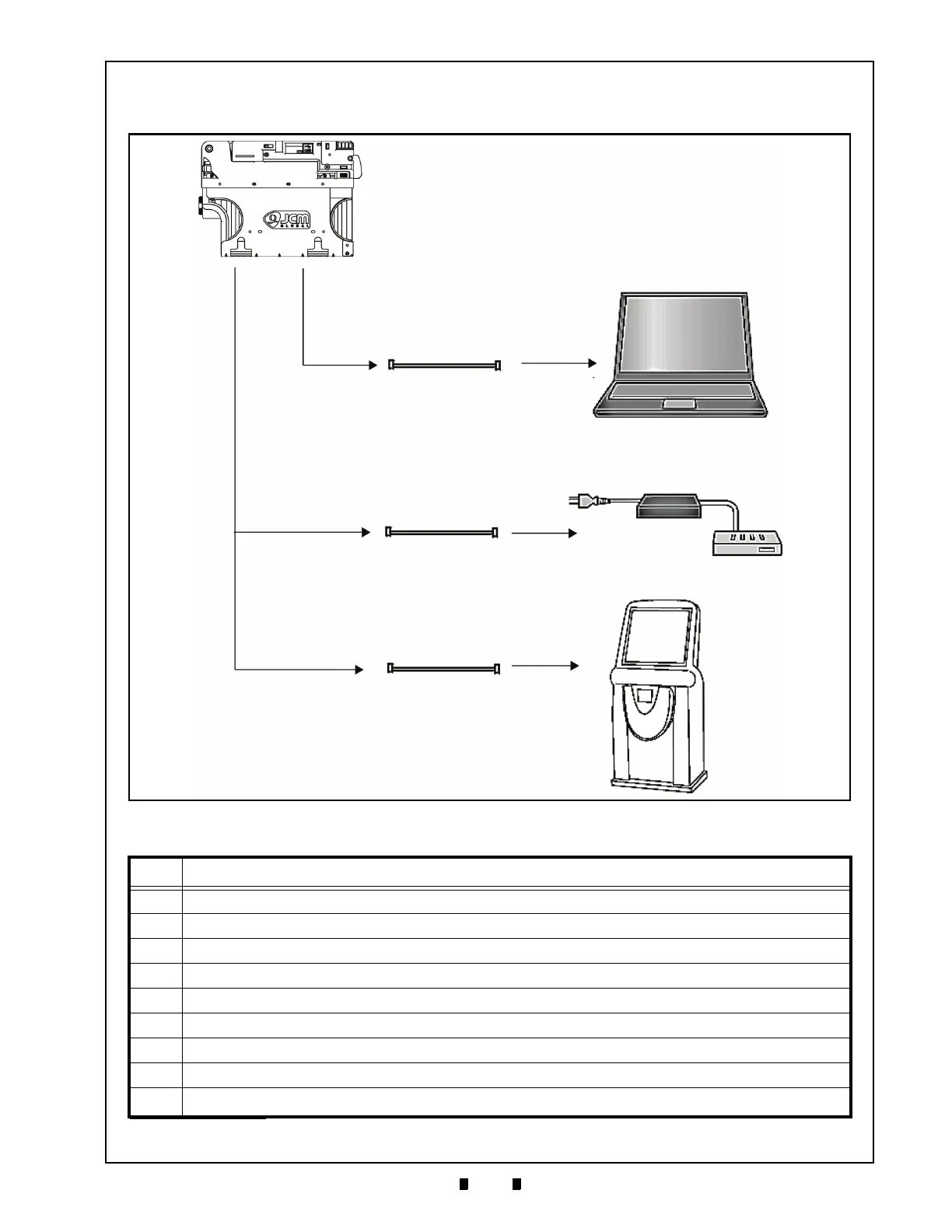
System Configurations
Figure 1-5 illustrates a typical VEGA system configuration.
Table 1-2: VEGA System Configuration List
Part Item
a VEGA Unit
b PC (Windows 2000/XP)
c Power Supply (e.g., UAC, MIB232, etc.)
d Host Machine (e.g., Game Machine,
Vending Machine etc.)
e Interface Connector (VEGA)
f Maintenance Connector (VEGA)
g Standard Marketplace USB Cable (to VEGA: Min
i B Plug/ to PC: Standard A Plug)
h Power Harness
i
Harness
a
a. User prepared interface Harness: Refer to “Connector Pin Assignments” on page 2-4 of Section 2 of this Manual for list of the required materials.
Figure 1-5 VEGA System Configuration with Host destination example

 Loading...


