P/N 960-100189RA_Rev. A {EDP #148850} © 2009, Japan CashMachine Co., Limited
Section 2 VEGA™ Series BankNote Validator Installation/Operation
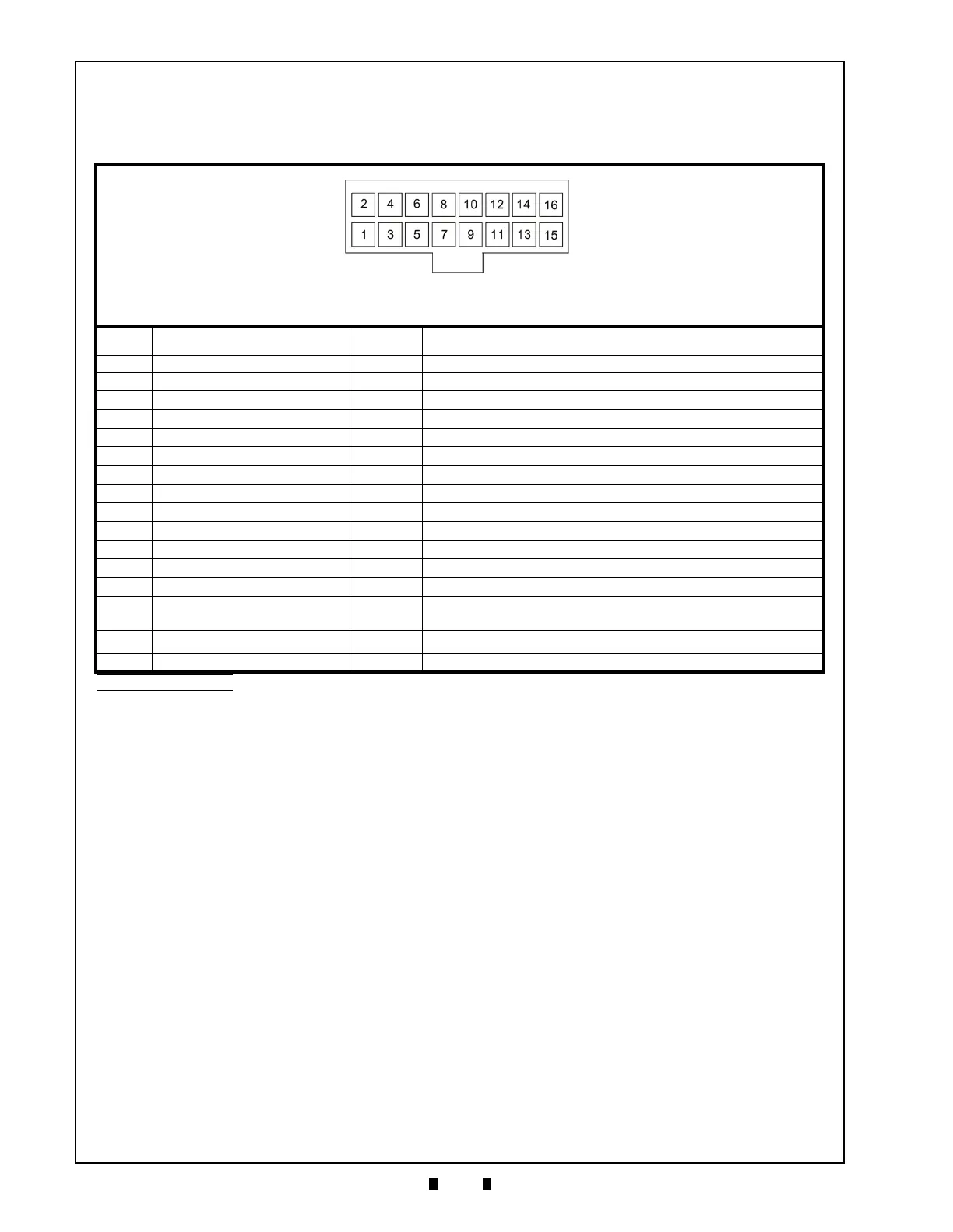
Table 2-4 VEGA Pin Assignments
VEGA Interface Connector
Box Pin Header: PS-16PE-D4LT1-PN (JAE)
Socket Housing: PS-D4C16
Contact Type: 030-51304-001
Recommended Wire: UL1007 AWG #24~26 (Slit Type)
Pin No. Signal Name
I/O
a
Function
1VDD1 --12V DC
2 VSS1 -- GND
3 RS232C-RXD IN Serial data signal input line from Controller to Validator
4 PC-RXD IN Serial data signal input line from Controller to Validator
5PC-TXD(MDB)OUTSerial data signal output line from Validator to Controller
6PC-COM --Photo-coupler Common (Ground)
7 VEND3(BUSY) OUT Serial data signal output line from Validator to Controller
8SG --Signal Ground
9 INHIBIT3(Soft-R) IN Serial data signal input line from Controller to Validator
10 INHIBIT4 IN Serial data signal input line from Controller to Validator
11 INHIBIT1 IN Serial data signal input line from Controller to Validator
12 INHIBIT2(D/E) IN Serial data signal input line from Controller to Validator
13 RTS/FULL OUT Serial data signal output line from Validator to Controller
14 VEND4(RS232C-TXD) OUT
Serial data signal output line from Validator to Controller
(
RS232C output line alternative)
15 VEND1(cc-Talk)
IN/
OUT
b
Serial data signal I/O line from Validator to Controller
16 VEND2(ABN) OUT Serial data signal output line from Validator to Controller
a. I/O (Input/Output) is the Terminal viewed from Banknote Validator’s Bezel opening.
b. ccTalk dual circuit use.
Connector Pin Assignments
Table 2-4 lists the VEGA Interface Connector Pin Assignments.
As Viewed From Front Side

 Loading...


